This post is also as PDF document available.
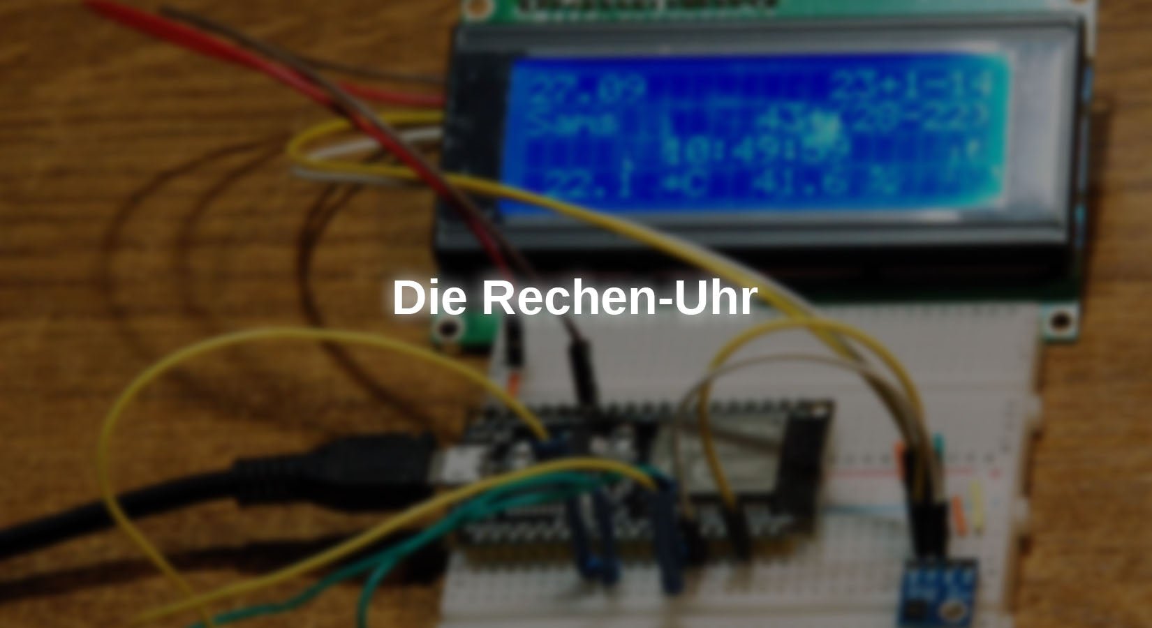
After the abacus clock with LED strips, this episode brings another clock variant just in time for the start of the new school year. It contributes to promoting mental arithmetic by not displaying the hours and minutes in plain text, as is usual with digital clocks, but in the form of small arithmetic tasks. The solution is displayed at the push of a button.
New tasks appear every minute. And to ensure that the time is always correct, the clock is synchronized every hour by accessing an NTP time server on the Internet. You'll find out how this works in today's article from the series
MicroPython on the ESP8266, ESP32 and Raspberry Pi Pico
today
The arithmetic clock
The structure is very clear. It consists of just four parts and a controller. This and another component, an SHT21 sensor for temperature and humidity measurement, live together on two breadboards that are plugged together along the long side. All models listed in the hardware list can be used as controllers. The program sniffs out the type used itself.
A large LCD display shows the date, day of the week, the arithmetic tasks, and at the push of a button the time, the room temperature and the relative humidity in the room. Another push button switches the background lighting on and off. If the lighting was off when you pressed the solution button, it will turn on for 10 seconds and then turn off again by itself.
Hardware

illustration 1: Construction with the ESP32 DEV Kit C V4
Figure 1 confirms the simple structure of the circuit with an ESP32. The button connector numbers are the same on all controllers, but have different positions on the board. This also applies to the I2C bus pins, which can be freely changed on the ESP32. At the Raspberry Pi Pico Different assignments are also possible, but only in very specific combinations. Although the structure for the ESP8266 family would be easy, but Unfortunately, the ESP8266's memory is too small for the program.
Here are the circuit diagrams for more information.

illustration 2: Circuit with ESP32

illustration 3: Circuit with Raspberry Pi Pico W
Since we want to access the WLAN, that's not the case Raspberry Pi Pico without “W”.
The software
For flashing and programming the ESP32:
Thonny or
Firmware used for the ESP32:
Firmware used for the Raspberry Pi Pico (W):
RPI_PICO_W-20240602-v1.23.0.uf2
The MicroPython programs for the project:
calculator.py: Clock operating program.
credentials_poly.py: WiFi credentials
hd44780u.py: Hardware driver LCD
lcd.py: API LCD
sht21.py: Driver module
ntp_test.py: Test and demo program for NTP access
sht-test.py: Test and demo program for LCD and SHT21 sensor
timeout.py: Set of non-blocking software timers
MicroPython - language - modules and programs
To install Thonny you can find one here detailed instructions (english version). There is also a description of how to do this Micropython firmware (as of January 25, 2024) on the ESP chip burned becomes. You can find out how to get the Raspberry Pi Pico ready for use here.
MicroPython is an interpreter language. The main difference to the Arduino IDE, where you always and exclusively flash entire programs, is that you only need to flash the MicroPython firmware once at the beginning on the ESP32 so that the controller understands MicroPython instructions. You can use Thonny, µPyCraft or esptool.py to do this. I have the process for Thonny here described.
Once the firmware is flashed, you can have a casual conversation with your controller, test individual commands, and immediately see the response without having to compile and transfer an entire program first. That's exactly what bothers me about the Arduino IDE. You save a lot of time if you can carry out simple syntax and hardware tests through to trying out and refining functions and entire program parts via the command line before you build a program out of it. For this purpose, I always like to create small test programs. As a kind of macro, they combine recurring commands. Entire applications sometimes develop from such program fragments.
Autostart
If you want the program to start autonomously when the controller is switched on, copy the program text into a newly created blank file. Save this file as main.py in the workspace and upload it to the ESP chip. The next time you reset or switch on, the program starts automatically.
Test programs
Programs are started manually from the current editor window in the Thonny IDE using the F5 key. This is faster than clicking on the start button or using the menu run. Only the modules used in the program must be in the flash of the ESP32.
Arduino IDE again in between?
If you later want to use the controller together with the Arduino IDE again, simply flash the program in the usual way. However, the ESP32/ESP8266 then forgot that it ever spoke MicroPython. Conversely, any Espressif chip that contains a compiled program from the Arduino IDE or the AT firmware or LUA or ... can easily be provided with the MicroPython firmware. The process is always like this here described.
A few tests in advance
Buttons, SHT21 and display
The SHT21 = HTU21 is located on the I2C bus together with the display adapter. This reduces the number of GPIO pins required. So together with the button connectors we need four. We'll start very slowly and simply.
The button thing isn't really that bad, one of the poles goes to the GPIO (GPIO14 and GPIO13), the other pole is connected to GND. We can save ourselves an external pull-up resistor because we use the internal one
>>> from machine import Pin
>>> light=Pin(14,Pin.IN,Pin.PULL_UP)
>>> loesung=Pin(13,Pin.IN,Pin.PULL_UP)
Button not pressed:
>>> licht()
1
Button pressed and held:
>>> licht()
0
Then it gets a little more complex. We connect the controller board to the SHT21 and to the display. The GPIOs for the three families are different. I am assuming the use of an ESP32 here.
ESP32: 5V – LCD: VCC (5V)
ESP32: 3V3 – GY-21: Vin
ESP32: GND – GY-21: GND – LCD: GND
ESP32: SCL (Pin 21) – GY21: SCL - LCD: SCL
ESP32: SDA (Pin 22) – GY21: SDA – LCD: SDA
When the connections are ready, we load the drivers for the display, hd44780u.py and lcd.py, down and then up into the controller's flash.

illustration 4: Upload files to Flash
We do the same with the file sht21.py. The file sht-test.py Let's save it in the project's working directory and open it in an editor window. After importing the required objects, we let go of the variable platform.platform whisper the type of controller and then set the pins for the peripherals. We have to limit the frequency for the I2C bus to 100,000Hz because of the display adapter with the PCF7485 serial-parallel converter.
# sht-test.py
from sys import exit, platform
from time import sleep_ms,sleep
from machine import Pin, SoftI2C, Timer
from sht21 import SHT21
from lcd import LCD
if platform == "esp32":
i2c=SoftI2C(scl=Pin(21),sda=Pin(22),freq=100000)
licht=Pin(14,Pin.IN,Pin.PULL_UP)
loesung=Pin(13,Pin.IN,Pin.PULL_UP)
elif platform == "rp2":
i2c=SoftI2C(scl=Pin(21),sda=Pin(20),freq=100000)
licht=Pin(14,Pin.IN,Pin.PULL_UP)
loesung=Pin(13,Pin.IN,Pin.PULL_UP)
else:
print("Nicht unterstuetzter Controller")
exit()
We wait 15 ms until the SHT21 has woken up from sleep and instantiate an SHT21 object. We then create an LDC object. The hardware address of the adapter board is set to 0x27, we have 20 columns and four rows. We turn off the cursor and turn on the backlight.
sleep_ms(15) # for booting SHT-Device
sh=SHT21(i2c)
d=LCD(i2c,adr=0x27,cols=20,lines=4)
d.cursorBlink(0)
d.cursor(0)
d.backLight(1)
Two functions, getEnvironment() and showEnvironment() ensure that the SHT21 measured values are acquired and output in REPL and on the display. The calculation routines place the values calculated from the raw data in the attributes sh.Temp and sh.Hum away.
def getEnvironment():
sh.readTemperatureRaw()
sh.calcTemperature()
sh.readHumidityRaw()
sh.calcHumidity()
def showEnvironment():
print(tempString.format(sh.Temp))
print(humString.format(sh.Hum))
d.writeAt(tempString.format(sh.Temp),2,3)
d.writeAt(humString.format(sh.Hum),12,3)
We announce the completion of the preparations, set a time delay between the value outputs and prepare the formatting strings for the output, 4 digits with one decimal place. The values appear after the program starts REPL and in the bottom line of the display.
print("Install done")
delay=3
tempString="{0:4.1f} C"
humString="{0:4.1f} %"
while 1:
getEnvironment()
showEnvironment()
sleep(delay)
d.clearAll()
SHT21 initialized @ 0X40
this is the constructor of HD44780U class
Size:20x4
Constructor of PCF8574U class
HWADR=0X27, Size=20x4
this is the constructor of LCD class
HWADR=0X27, Size:20x4
Install done
21.8C
43.4 %
21.8C
43.3 %
…
Now we can also readjust the contrast on the trim pot of the display adapter.
WiFi connection, NTP server query and timestamps
The program ntp_test.py shows how to use the module network, which can connect to a WiFi router/access point. The way the program works and its objects and functions are in the PDF document wireless connections with a WLAN in the chapter Interface objects and functions exactly described, which is why I recommend reading this tutorial. Information about the program ntp_test.py can also be found in the above PDF document in the chapter Contact an NTP server.
For WiFi login I use a file named credentials_poly.py. It contains the access data for one or more WLAN nodes. The controller tries to contact them one after the other. The search will be canceled as soon as a connection is established. The structure of the file credentials_poly.py is in the chapter The credentials file in the PDF document described. Of course, you have to enter your own access data there instead of the dummy values. The processes involved in establishing a connection in the main program can be found in the chapter Preparations in the main program, the description of the main loop itself is in the chapter The main loop to find.
# ntp_test.py
import ntptime as ntp
import network
from time import sleep, localtime, gmtime, mktime
from credentials_poly import *
from timeout import TimeOutMs
from sys import exit
from machine import Pin, RTC
displayPresent=False
timeZone=1
connectStatus = {
1000: "STAT_IDLE",
1001: "STAT_CONNECTING",
1010: "STAT_GOT_IP",
202: "STAT_WRONG_PASSWORD",
201: "NO AP FOUND",
5: "UNKNOWN",
0: "STAT_IDLE",
1: "STAT_CONNECTING",
5: "STAT_GOT_IP",
2: "STAT_WRONG_PASSWORD",
3: "NO AP FOUND",
4: "STAT_CONNECT_FAIL",
}
def hexMac(byteMac):
"""
Die Funktion hexMAC nimmt die MAC-Adresse im Bytecode und
bildet daraus einen String fuer die Rueckgabe
"""
macString =""
for i in range(0,len(byteMac)): # Fuer alle Bytewerte
val="{:02X}".format(byteMac[i])
macString += val
if i <len(byteMac)-1 : # Trennzeichen
macString +="-" # bis auf letztes Byte
return macString
def connect2router(entry): # n = Connection-Set-Nummer
# ************** Zum Router verbinden *******************
nic=network.WLAN(network.AP_IF)
nic.active(False)
nic = network.WLAN(network.STA_IF) # erzeugt WiFi-Objekt
nic.active(True) # nic einschalten
MAC = nic.config('mac')# binaere MAC-Adresse abrufen und
myMac=hexMac(MAC) # in Hexziffernfolge umwandeln
print("STATION MAC: \t"+myMac+"\n") # ausgeben
sleep(2)
nic.ifconfig((creds[entry]["myIP"],
creds[entry]["myMask"],
creds[entry]["myGW"],
creds[entry]["myDNS"]))
if not nic.isconnected():
nic.connect(creds[entry]["mySSID"],
creds[entry]["myPass"])
print("Status: ", nic.isconnected())
if displayPresent:
d.clearAll()
d.writeAt(creds[entry]["mySSID"],0,0)
points="." * 10
n=1
while nic.status() != network.STAT_GOT_IP:
print(".",end='')
if displayPresent: d.writeAt(points[0:n],0,1)
n+=1
sleep(1)
if n >= 10:
if displayPresent:
d.writeAt(" NOT CONNECTED ",0,1)
print("\nNot connected")
nic.active(False)
nic=None
return None
print("\nStatus: ",connectStatus[nic.status()])
if displayPresent: d.clearAll()
STAconf = nic.ifconfig()
print("STA-IP:\t\t",STAconf[0],"\nSTA-NETMASK:\t",\
STAconf[1], "\nSTA-GATEWAY:\t",STAconf[2] ,sep='')
print()
if displayPresent:
d.writeAt(STAconf[0]+":"+str(creds[entry]["myPort"]),0,0)
d.writeAt(creds[entry]["mySSID"],0,1)
return nic
def inTheSummertime(jahr,monat,tag):
if monat < 3 or monat > 10:
return timeZone
if 3 < monat < 10:
return timeZone + 1
letzterMaerzSonntag = max([mtag for mtag in range(25,32) \
if gmtime(mktime((jahr, 3, mtag, 2, 0, 0, 0, 0, 0)))[6] == 6])
letzterOktSonntag = max([mtag for mtag in range(25,32) \
if gmtime(mktime((jahr, 10, mtag, 2, 0, 0, 0, 0, 0)))[6] == 6])
if monat == 3 and tag >= letzterMaerzSonntag:
return timeZone + 1
if monat == 10 and tag < letzterOktSonntag:
return timeZone + 1
return timeZone
entry=None
for i in range(len(creds)):
print("\n\n",creds[i]["mySSID"])
if creds[i]["myIF"] == "STA":
nic = connect2router(i)
if nic is not None:
entry=i
break
taste=Pin(0,Pin.IN, Pin.PULL_UP)
r=RTC()
while 1:
try:
sekunden=ntp.time()
year,month,day=gmtime(sekunden)[0:3]
offset=inTheSummertime(year,month,day)
# ntp.time() liefert Anzahl Sekunden seit
# Epochenbeginn (01.01.1900)
tag=localtime(sekunden+offset*3600)
print("NTP-Time ",tag)
# NTP-Format
# year,month,day,hor,minute,second,dow,_
except:
print("Uebertragungsfehler")
sleep(1)
if taste() == 0:
exit()
We're starting the program now ntp_test.py in an editor window.
>>> %Run -c $EDITOR_CONTENT
ARCTURUS
STATION MAC: 10-52-1C-02-50-24
Status: STAT_GOT_IP
STA IP: 10.0.5.199
STA NETMASK: 255.255.255.0
STA GATEWAY: 10.0.5.20
NTP time (2025, 9, 27, 19, 15, 31, 5, 270)
NTP time (2025, 9, 27, 19, 15, 32, 5, 270)
NTP time (2025, 9, 27, 19, 15, 33, 5, 270)
We have already covered a large part of the project with the last two programs. We will find the parts in the main program in a moment, but we will skip them for the discussion now.
The watch program
What we're still missing are a few little things to control the process and of course the professor who dynamically sets the calculation tasks. Always doing the same tasks would be boring! It's best to download the program straight away calculator.py Download and open it in a Thonny editor window. This will make it easier for you to locate and classify the parts that need to be discussed. The import list has grown a bit. The first three lines are the most important. The first is used to generate random numbers. Then we get support for a hardware timer and the internal one RTC of the controller. Finally, there are some functions for time format conversion.
from random import *
from machine import Pin,SoftI2C,Timer,RTC
from time import sleep,sleep_ms,localtime, gmtime, mktime
import network
import ntptime as ntp
from credentials_poly import creds
from sys import exit, platform
from timeout import TimeOut
from sht21 import SHT21
The selection of the platform is already known, as is the creation of the SHT21 object. What is new, however, is the creation of a hardware timer object t0.
if platform == "esp32":
t0=Timer(0)
i2c=SoftI2C(scl=Pin(21),sda=Pin(22),freq=100000)
licht=Pin(14,Pin.IN,Pin.PULL_UP)
loesung=Pin(13,Pin.IN,Pin.PULL_UP)
elif platform == "rp2":
t0=Timer()
i2c=SoftI2C(scl=Pin(21),sda=Pin(20),freq=100000)
licht=Pin(14,Pin.IN,Pin.PULL_UP)
loesung=Pin(13,Pin.IN,Pin.PULL_UP)
else:
print("Nicht unterstuetzter Controller")
exit()
The instantiation of a is also new RTC and the milking of local time. The tuple contains the date and time as well as the day of the week. The indices in that Tuple are defined as constants. In the list weekday let's record the "names" of the days of the week. We are in time zone 1. We synchronize our RTC approximately every 60 minutes. We set the counter to 0.
rtc=RTC()
dt=rtc.datetime()
anno=const(0)
mon=const(1)
mday=const(2)
wday=const(3)
hor=const(4)
mnt=const(5)
sec=const(6)
wochentag=[
"Mont",
"Dien",
"Mitt",
"Donn",
"Frei",
"Sams",
"Sonn"
]
timeZone=1
refreshPoint=60 # Minuten zur naechsten Synchronisation
refreshCnt=0
Now it goes in big leaps over familiar parts. We end up on line 149. Tick() is the ISR the hardware timer t0 and it will be called when the timer has expired. Here only the flag ticked on True set. ticked is used in the main loop to output the time.
def tick(t0):
global ticked
ticked = True
inTheSummertime() we already know from ntp-test.py. The function increases the time zone value by 1 compared to GMT during daylight saving time.
def inTheSummertime(jahr,monat,tag):
if monat < 3 or monat > 10:
return timeZone
if 3 < monat < 10:
return timeZone + 1
letzterMaerzSonntag = max([mtag for mtag in range(25,32) \
if gmtime(mktime((jahr, 3, mtag, 2, 0, 0, 0, 0, 0)))[6] == 6])
letzterOktSonntag = max([mtag for mtag in range(25,32) \
if gmtime(mktime((jahr, 10, mtag, 3, 0, 0, 0, 0, 0)))[6] == 6])
if monat == 3 and tag >= letzterMaerzSonntag:
return timeZone + 1
if monat == 10 and tag < letzterOktSonntag:
return timeZone + 1
return timeZone
Start again for the following experiments ntp-test.py and break with it CTRL + C away. This gives you the environment in which the following inputs work, a connection to the time server, the function inTheSummertime() and the tools from the module time. First we determine the beginning of the epoch. Then we get the number of seconds since the start of the epoch and convert the value into a more readable format.
>>> gmtime(0)
(2000, 1, 1, 0, 0, 0, 5, 1)
>>> ntp.time()
812355151
>>> gmtime(812355151)
(2025, 9, 28, 6, 12, 31, 6, 271)
>>> gmtime(812355151)[0:3]
(2025, 9, 28)
With slicing we get the first three elements from the tuple that gives us gmtime() returns year, month and day after the seconds have been converted. We pass this tuple to inTheSummertime()
This function now determines the day numbers of the last Sunday in March and the last Sunday in October, if the month number is not already between 4 and 9 inclusive. Otherwise, if the current date is after the last Sunday in March (incl.) and before the last Sunday in October, the value of is used in all these cases timezone increased by 1.
>>> inTheSummertime(2025, 9, 28)
2
>>> inTheSummertime(2025, 11, 3)
1
But what does synchronize()? With every call from synchronize() the RTC of the ESP32 is set to the current time, of course taking the time zone and the daylight saving time offset into account.
We get the seconds since the beginning of the era. This is January 1, 2000, as we noted above. gmtime(seconds) converts the seconds value into a timestamp in the form of a tuple:
(year, month, day, hours, minutes, seconds, day of the week, anniversary)
We unpack the partial tuple (year, month, day) obtained by slicing and pass the three values inTheSummertime(). Then we correct the seconds by the offset value in seconds. gmtime(seconds) provides the corrected timestamp for our time zone, which we immediately break down into the individual values. This is necessary for re-sorting because the RTC format differs from the GMT format.
(year, month, day, day of the week, hours, minutes, seconds, microseconds)
With the changed order we set the RTC time. This all happens within the try-Blocks to catch any errors, what with except OSError happens.
refreshCnt we have at the beginning as global declared so that the value changed to 0 is known in the main program.
def synchronize():
global refreshCnt
try:
sekunden=ntp.time()
year,month,day=gmtime(sekunden)[0:3]
offset=inTheSummertime(year,month,day) # offset=zeitzone+0/1
sekunden += offset*3600 # Zeitzone und Sommer/Winterzeit
Y,M,D,h,m,s,dow,doy=gmtime(sekunden)
rtc.datetime((Y,M,D,dow,h,m,s,0))
print("synchronized: ",rtc.datetime())
except OSError as e:
print("Synchron-Fehler",e)
refreshCnt=0
In addition to the environment values, the date and time must also be output, with hours and minutes being coded as a calculation task. Done the ad yourself showDateTime(). We pass a date-time tuple to the function.
def showDateTime(dt):
d.clearFT(0,0,19,1)
d.writeAt("{:0>2}.{:0>2}".format(dt[mday],dt[mon]),0,0,False)
d.writeAt(wochentag[dt[wday]],0,1)
i=randint(0,len(terme)-1)
s=terme[i](dt[hor])
print("Stunde"," index",i,"Term:",s,"Stunde:",dt[hor])
pos=d.columns - len(s)
d.writeAt(s,pos,0)
i=randint(0,len(terme)-1)
s=terme[i](dt[mnt])
print("Minute"," index",i,"Term:",s,"Stunde:",dt[mnt])
pos=d.columns - len(s)
d.writeAt(s,pos,1)
After deleting the top two lines in the display, we output the date at the top left and the abbreviation of the day of the week below. randint() determines a "random", integer number between the passed values (incl.). I use the function twice to roll one out of a series of functions. We'll get to know the magic behind MicroPython later. The goal of this randomly selected function is to generate a term that is to be displayed right-aligned for the hour and minute values on the right edge of the display. The term comes back as a string and becomes the variable s assigned. The start position for the output is the difference between the number of columns on the display, d.columns, and the length of s. The print statements help with program development and can also be omitted.

illustration 5: arithmetic problems

illustration 6: Calculation problems with solutions
getEnvironment() and showEnvironment() are already known, so we go straight to line 210. From here come the definitions of the functions that generate the terms. Function plays a role here too randint() again plays an important role several times. In each case at least one random number (x or x and y) must be determined. On the other hand, the value for z to be transferred is always fixed by the hour or minute that should result. Because the various arithmetic operations +, -, • and : will rarely result in the value of z through random values alone, we need a variable, adjustable value everywhere, which I have called a. Example:
Term: x + a = z mit dem Zufallswert x, der zwischen 0 und z liegen soll.
x=randint(0,z)
Daraus berechnen wir a.
a=z-x
Schließlich bauen wir alles zu einem String zusammen, den wir zurückgeben.
s="{}+{}".format(x,a)
return s
Alles zusammen:
def term0(z):
x=randint(0,z)
a=z-x
s="{}+{}".format(x,a)
return s
Hours run from 0 to 23, minutes from 0 to 59. We have to classify zero as a special case if it indicates problems.
def term0(z):
x=randint(0,z)
a=z-x
s="{}+{}".format(x,a)
return s
Term: x – a = z O a = x – z; with x > z
x = randint(z,2*z); but randint(0,0) returns a runtime error
So we simply sort out the case z = 0 using the if construct and return 0. The situation is similar for the other 13 functions.
Now we come to the magic of MicroPython. How do I select a function from several? The crude solution is an if-elif-elif… construct, which matches a randomly rolled number and calls the corresponding function. This solution is cumbersome, large and poorly scalable. The more elegant solution uses a list whose elements are the identifiers of the termx functions. We find the definition starting from line 357.
terms = [term0,
term1,
term2,
term3,
term4,
term5,
term6,
term7,
term8,
term9,
term10,
term11,
term12,
term13,
term14,
term15,
]
Thus, terme[5](z) calls the function term5(z) with the argument z. In MicroPython, functions are objects. And one list can even contain elements of completely different types. The indexing dynamically replaces a rigid structure of around 45 lines with one line. We use that in showDateTime().
We can use the function to determine whether the termx functions work and the terms deliver the correct value z testTerms() check. Every termx function is called for every number between 0 and 23 inclusive. We determine the function and thus the term as a string.
term=terms[i]
s=term(val)
Then we output the term number, the string s and the term value, which we pass through eval() can be calculated from the string. The latter is again a piece of MicroPython magic.
>>> val=17
>>> i=4
>>> term=terms[i]
>>> s=term(val)
>>> i
4
>>> s
'-7+8*3'
>>> eval(s)
17
Voices val and eval(s) does not match, the function aborts and reports the error. If the function runs to the end, we can be sure that the terms are created correctly.
We form the format strings in a known manner, synchronize the RTC, set the flag ticked back and clear the display.
tempString="{0:4.1f} *C"
humString="{0:4.1f}%"
synchronize()
ticked=False
d.clearAll()
Then we get a timestamp and have the date, the calculation tasks and the environment values displayed on the display.
dt=rtc.datetime()
showDateTime(dt)
getEnvironment()
showEnvironment()
The display is updated every minute. That's why we set the update timer t0 to 60,000 milliseconds = 1 minute. It runs periodically and starts the ISR when it expires Tick().
t0.init(period=60000,mode=Timer.PERIODIC,callback=tick)
weiter=TimeOut(0)
We also set the software timer further to False. Time-out() returns a function that represents a timer. This function we assign the identifier further to. further() delivers False back as long as the timer has not yet expired, otherwise True. With the call continue(0) we'll get it until St. Never's Day False back.
Now let's go back to the timer t0 back. It expires after 1 minute and then calls the ISR Tick(). This in turn sets the flag ticked on True. And we query exactly this flag in the main loop. This is where the main work is done. Because we want to keep an ISR as short as possible, we delegate the sequence to the main loop.
If ticked True the display must be rebuilt. To do this, we completely delete the display and set ticked immediately again False. Then we get a timestamp and the surrounding values. The date is output in plain text, the time in the form of two calculation tasks. The environment values are then output.
while 1:
if ticked:
d.clearAll()
ticked = False
dt=rtc.datetime()
getEnvironment()
showDateTime(dt)
showEnvironment()
refreshCnt += 1
if refreshCnt == refreshPoint:
synchronize()
The refresh counter is incremented. Once we have reached the limit, the RTC is synchronized with the NTP server, which happens every 60 minutes.
With the solution key, the current time is displayed in plain text in line 2. If the backlight was off, it will now turn on and the expiration timer will be set to 10 seconds. The light turns off when the timer expires.
if loesung() == 0:
if d.backLight() == 0:
d.backLight(1)
weiter=TimeOut(10)
d.writeAt("{:0>2}:{:0>2}".format(dt[hor],dt[mnt]),8,2)
With the button light we can turn the backlight on and off.
if licht() == 0:
if d.backLight() == 0:
d.backLight(1)
else:
d.backLight(0)
sleep(0.2)
The timer further() is the core for automatically switching off the backlight. Delivers the Closure, which is behind everything True back, the timer has expired and we delete the plain text time and the backlight. The timer further has to be on again permanently False be set because otherwise the light cannot be switched on permanently.
if weiter():
d.clearFT(6,2,13,2)
d.backLight(0)
weiter=TimeOut(0)
The program can be canceled using the flash button on the ESP32 board if nothing else works.
if taste() == 0:
d.backLight(0)
exit()
Now I hope you enjoy setting it up and programming it. For example, you can design new terms, sort them according to difficulty groups or install a timer that automatically displays the solution after 50 seconds when a new task appears.


4 commenti
Rainer Liebenstein
Hallo Herr Grzesina,
vielen Dank für die schnelle Hilfe! Alles funktioniert jetzt (Beleuchtung und Lösung)! Super Idee diese Rechenuhr. Als nächstes werde ich mir mal die Abakus-Uhr näher ansehen.
Danke und viele Grüße
Rainer Liebenstein
Jürgen
@ Rainer Liebenstein
Ich habe grade das Programm heruntergeladen (hätte ich auch schon eher draufkommen können!) . Der Übeltäter ist tatsächlich eine exit()-Zeile und zwar Zeile 419. Bitte auskommentieren, oder noch besser, das Programm neu herunterladen, ich habe die Stelle korrigiert.
Entschuldigung, den Fehler habe ich selbst verursacht. Ich verwende die exit()-Anweisung gerne während der Programmentwicklung und habe die Zeile zum Schluss leider nicht wieder herausgenommen.
Jürgen
Jürgen
Hallo, Herr Liebenstein,
An den Kurzhubtasten kann es sehr wahrscheinlich nicht liegen, die
arbeiten korrekt.
Ist der zweite Tasteranschluss sicher mit GND des
ESP32 verbunden? Was tut sich, wenn Sie ein Voltmeter an den GPIO-Pin
und an GND anschließen?
Taster offen → ca. 3,3 V
Taster gedrückt → 0 V
Wenn die Tasten nicht ansprechen, kann weder das Licht geschaltet,
noch die Lösung aufgerufen werden. Also muss dieses Problem in der
Tasterabfrage liegen. Wie reagiert bei Ihnen folgende Sequenz auf
Tastendruck (Siehe auch “Tests im Vorfeld” im Blog).
>>> from machine import Pin
>>> licht=Pin(14,Pin.IN,Pin.PULL_UP)
>>> licht() # kein Tastendruck!
1
>>> # Taste drücken und halten
>>> licht()
0
Wie ist die Sachlage, wennn Sie den Tastenkontakt mit einem Jumperkabel
überbrücken?
>>> licht()
0
Wie sieht es aus, wenn Sie einen anderen Pin als Eingang nehmen? Aber bitte nicht
GPIO15, das kann nicht funktionieren, weil der Pin als Eingang ungeeignet ist,
warum auch immer?
Das Updaten der Uhrzeit in Aufgabenform hängt mit dem Hardwaretimer t0 zusammen.
Der gibt das Intervall in Millisekunden vor, in dem die Anzeige erneuert werden soll.
Den Aufruf der ISR tick() können Sie überprüfen, wenn Sie eine Zeile einfügen.
>>> t0=Timer(0)
>>> def tick(t0):
global ticked
ticked = True
print(“Tick”) # Ausgabe in REPL
Dem Timer geben Sie die Sporen, wenn Sie ihn wie folgt initialisieren:
>>> t0.init(period=1000,mode=Timer.PERIODIC,callback=tick)
Jetzt sollte im Sekundenabstand “Tick” in REPL erscheinen.
Tick
Tick
Tick
Tick
Tick
Tick
Tick
t0.deinit()
Wenn alle bisher beschriebenen Tests funktionieren, dann können
die von Ihnen beschriebenen Probleme auch auftreten,
wenn die Hauptschleife nicht erreicht wird oder nicht korrekt arbeitet.
Suchen Sie im Programmlisting nach nicht auskommentierten “exit()”-Zeilen.
Kommentieren Sie die Zeilen aus öder löschen Sie sie. Programm starten…
Fügen Sie eine print-Anweisung als letzte Zeile vor Beginn der Hauptschleife
als Zeile 415 ein. und starten Sie das Programm. Wird der Text “Vorbereitung OK”
in REPL angezeigt?
weiter=TimeOut(0)
exit() # <<<<<< auskommentieren oder löschenprint(“Vorbereitungen OK”) # <<<<< einfügen <<<<<
Erscheint der Text, dann fügen Sie eine weitere Zeile gleich unterhalb von while 1: ein,
wenn das Programm immer noch nicht ordentlich läuft.
while 1:
print(“Schleife läuft”) # <<<<< einfügen <<<<<
if ticked:
…
synchronized: (2025, 10, 20, 0, 14, 37, 46, 95)
Stunde index 15 Term: 25+19-30 Stunde: 14
Minute index 2 Term: 19+27-9 Stunde: 37
19.5 *C
42.1 %
Vorbereitungen OK
Schleife läuft
Schleife läuft
Schleife läuft
Schleife läuft
Schleife läuft
Ich gehe davon aus, dass spätestens jetzt die Uhr das tut was sie soll. Die Schleife muss laufen, damit die Tasten abgefragt werden und der Rest erledigt wird.
Falls nicht, geben Sie mir Bescheid, dann suchen wir weiter.
Rainer Liebenstein
Hallo Herr Grzesina,
obwohl ich seit Jahren nur Erfahrungen mit ARDUINO gemacht habe, hat mich Ihr Projekt sehr interessiert und es ist mir, zumindest teilweise, gelungen es zu realisieren.
Allerdings sind ein paar Probleme bzw. Fragen aufgetaucht. Ich hoffe Sie können weiterhelfen.
Beide Tasten funktionieren leider nicht: Die Displaybeleuchtung ist dauerhaft an, die Lösung für die Uhrzeit wird nicht angezeigt. Ich habe zwar nicht die von Ihnen vorgestellten Drucktaster verwendet, sondern die kleinen „Breadbord-Taster“ (Schließer); aber daran dürfte es wohl nicht liegen? Das Display ist ein HD44780 2004 mit I2C-Schnitt-stelle, 4×20 Zeichen.
Ich habe auch die „main.py-Datei“ erstellt und auf den ESP32 (Dev Kit C V4) hochgeladen.
Der ESP 32 fährt nach Anlegung der Spannung automatisiert hoch und zeigt die gerade
aktuelle Uhrzeit mittels Rechenaufgabe an, sowie das korrekte Datum, den Wochentag, den Luftdruck und die Temperatur.
Allerdings erscheinen nicht wie in der Anleitung beschrieben, nach einer Minute neue Rechenaufgaben, d.h. die zunächst angezeigte Uhrzeit wird nicht „fortgeschrieben“. Was könnte die Ursache sein?
Für Ihre Unterstützung schon jetzt vielen Dank.
Mit freundlichen Grüßen aus Würzburg
Rainer Liebenstein