In the previous contribution If we examined the function of the neopixel strip more closely and thought about how the coding of times could be implemented. We have also dealt with the different formats in which the functions Time.localTime () and rtc.dateTime () represent the date and time. Both modules manage the time in the background in the form of a meter who records the seconds since the beginning of the era. This meter state is brought into a legible form by the two functions, only in different ways.
But who actually tells our controller at the start how much clock it did? And how can an ESP32 overtime make sure that its count also corresponds to the statutory period? We will clarify this in the current episode from the series
Micropython on the ESP32 and Raspberry Pi Pico
today
The Abakus watch gets support
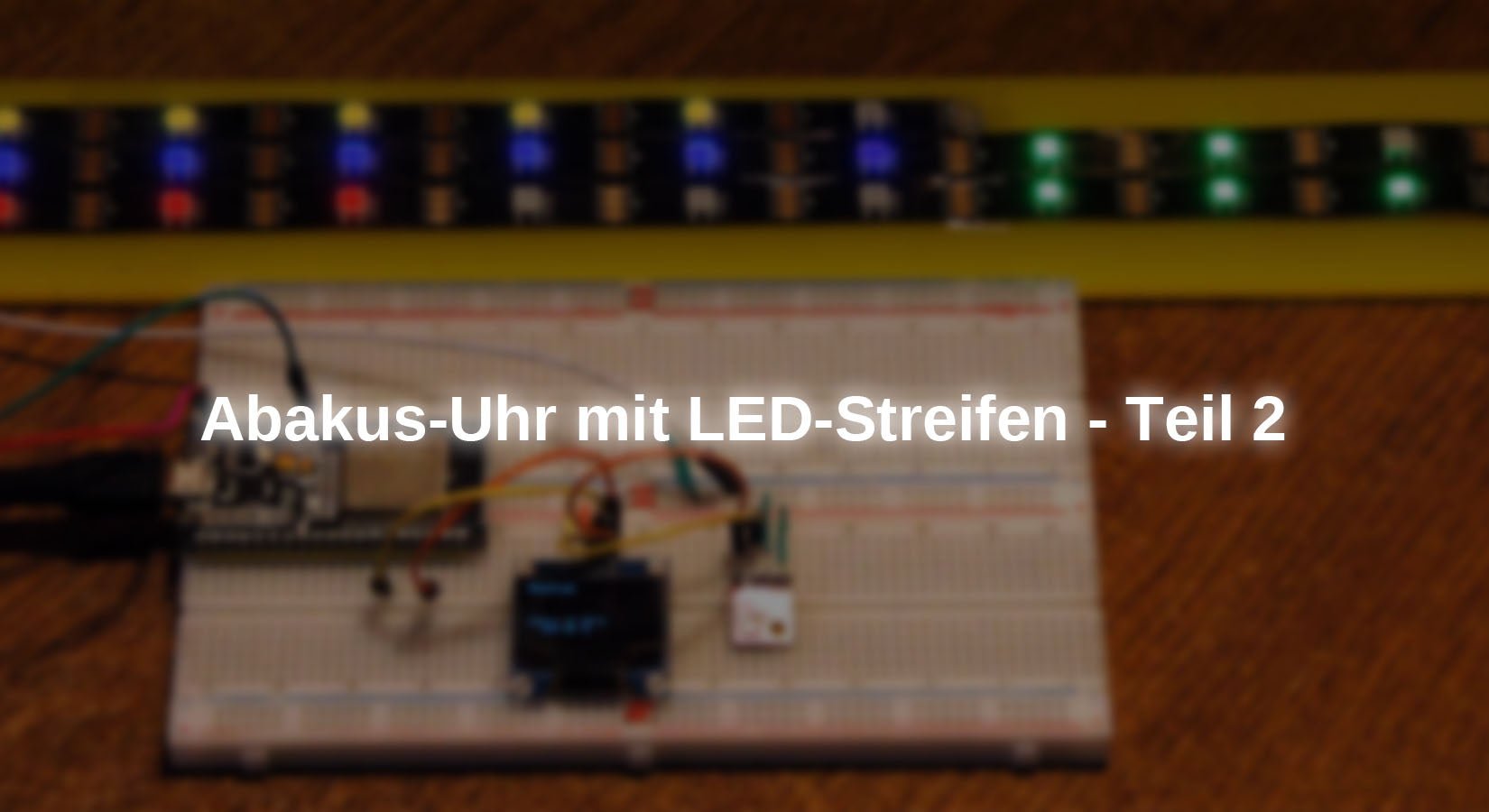
In this article, an OLED display with 128x64 pixels and a BME280 for recording environmental data such as temperature, air pressure and relative humidity is also installed. We use the following parts.
Hardware
|
1 |
ESP32 Dev Kit C V4 unplacerated or |
|
1 |
Or |
|
1 |
|
|
1 |
Optional for Raspberry Pi Pico W Button, for example Ky-004 button module |
|
1 |
|
|
Optional |
|
|
Optional |
An ESP8266 would also have been sufficient for expansion levels 1. Because there is a BME280 in this new episode, the little one is unfortunately too weak on the memory breast, which is why an ESP32 is used here. Optionally a Raspberry Pi Pico W take over the control. Like the ESP32, it is also capable of WLAN, which we need in level 2 for a connection to an NTP server on the Internet.
With a Logic Analyzer, the signals on the Neopixel bus or the I2C bus can be made very clearly visible. This is particularly helpful when problems arise or if you want to study the behavior of neopixel arrays and the transfer on the I2C bus.
The Charger Doctor enables the monitoring/measurement of voltage and electricity on the USB bus and above all tell us the current requirement of the circuit.
This is what the structure of level 2 looks like.

illustration 1: LED strip clock with BME280 and OLED
And here are the circuit diagrams for the two controllers.

illustration 2: Abacus clock with ESP32 expansion level 2 switching sketch

illustration 3: Abacus clock with Raspberry Py Pico W expansion level 2 switching sketch
In all cases, the control line for the neopixels is GPIO14, so that no changes are necessary on the program that we will shortly discuss. However, we have to take into account the I2C connection. The SCL and SDA lines can be assigned to GPIOS at the ESP32. At the Raspberry Pi Pico In contrast, only certain GPIO pairs are available. The problem is rather marginal. We make it!
The software
For flashing and the programming of the ESP32:
Thonny or
To represent bus signals
Saleae – Logic analyzer software (64 bit) For Windows 8, 10, 11
Used firmware for the ESP32:
Used firmware for the Raspberry Pi Pico (W):
Rpi_pico_w-20240602-V1.23.0.uf2
The micropython programs for the project:
o'clock.py Provenema for the clock
o'clock2.py Provenema for the clock
ntp_test.py Test connection to an NTP server
rtc_time.py Module for the implementation of time structures
bme280.py Hardware driver module for the BME280
SSD1306.PY Hardware driver module for the OLED 128x64
oled.py API for the comfortable text control of the display module
Micropython - Language - Modules and Programs
To install Thonny you will find one here Detailed instructions (English version). There is also a description of how that Micropython firmware (As of 01/25/2024) on the ESP chip burned becomes. How to get the Raspberry Pi Pico ready for use here.
Micropython is an interpreter language. The main difference to the Arduino IDE, where you always flash entire programs, is that you only have to flash the Micropython firmware once on the ESP32 so that the controller understands micropython instructions. You can use Thonny, µpycraft or ESPTOOL.PY. For Thonny I have the process here described.
As soon as the firmware has flashed, you can easily talk to your controller in a dialogue, test individual commands and see the answer immediately without having to compile and transmit an entire program beforehand. That is exactly what bothers me on the Arduino IDE. You simply save an enormous time if you can check simple tests of the syntax and hardware to trying out and refining functions and entire program parts via the command line before knitting a program from it. For this purpose, I always like to create small test programs. As a kind of macro, they summarize recurring commands. Whole applications then develop from such program fragments.
Autostart
If the program is to start autonomously by switching on the controller, copy the program text into a newly created blank tile. Save this file under main.py in the workspace and upload them to the ESP chip. The program starts automatically the next time the reset or switching on.
Test programs
Programs from the current editor window in the Thonny-IDE are started manually via the F5 button. This can be done faster than the mouse click on the start button, or via the menu run. Only the modules used in the program must be in the flash of the ESP32.
In between, Arduino id again?
Should you later use the controller together with the Arduino IDE, just flash the program in the usual way. However, the ESP32/ESP8266 then forgot that it has ever spoken Micropython. Conversely, any espressif chip that contains a compiled program from the Arduino IDE or AT-Firmware or Lua or ... can be easily provided with the micropython firmware. The process is always like here described.
Experiments on the time jungle
Today we will be dealing with three systems for the time management, the local system time (LocalTime), RTC (Real Time Clock = real -time clock) and NTP (Network Time Protocol). We briefly illuminated the first two in the last post. We found that the structures, such as the date and time are displayed, are similar but not congruent. On the other hand, both modules apply time.localime() and Rtc.dateTime() towards the same source of time. This is the count of seconds since the beginning of the era or era.
When starting the ESP32 on the USB bus of the PC, the controller automatically receives the number of seconds and then provides its watch. That is why the program shows o'clock.py, which we wrote for the LED strip, the correct time right from the start. Ultimately, our development environment Thonny ensures this. If we do not connect the circuit to the PC, but let it run autonomously, what happens then?
Let's try it out, youth research! So that the controller can start autonomously, we have to o'clock.py Load into the editor and with "Save under" with the name main.py Upload to the flash of the ESP32. If this is done, we connect the structure to a 5V voltage source.
ESP-PIN 5V on battery plus
ESP GND PIN on battery minus
So we would do it if we later operated the circuit alone. Only now we now find that the time displayed does not match the current time. No, the count starts at 00:00:00! Even if we now connect the ESP32 to the PC instead of the battery, the count begins again at 00:00:00. Because the program is automatically launched by the firmware of the ESP32, this does not feel any reason to enter a cozy chat with the PC.
As soon as we interrupt the program with the Flash key (we have built this option to be on the safe side ;-)), and again the program o'clock.py Starting in Thonny, the time synchronization also works.
Conclusion:
We have to ensure that our watch is synchronized when booting without a connection to the PC. This is exactly what we do with the help of a time server on the Internet.
Before that, however, a few facts about the three time systems that go beyond the presentation.

illustration 4: Interaction of time systems
The time manager on the ESP32 is clearly the RTC. She manages the second counter and also masters the conversion of seconds into an RTC time structure and vice versa. Only the second value that is held in the RTC can be changed from the outside, from the PC, from a micropython program and via access to an NTP server. So the RTC is legible and writing. The system time is synchronized via the RTC and can only be read out. However, you can use the function time.localime() handed over an argument, a second value, which is then converted into a time structure. This is practical if you want to calculate times in the future or past. The functions can also be used for this time.mktime() and time.gmTime() to be used. The former creates a second value from a time tupel, the second works the other way around and turns a second value a time structure. We are now taking a few examples of this in Replica to. We start importing the ingredients.
>>> From Time Import LocalTime, GMTime, MkTime
>>> From Machine Import RTC
Then we ask the system time and receive a time structure tupel, it has the following form.
(Y, M, D, H, M, S, Dow, Doy)
>>> LocalTime ()
(2025, 4, 5, 18, 14, 9, 5, 95)
From this we make the seconds of the era
>>> MkTime ((2025, 4, 5, 18, 14, 9, 5, 95))
797192049
And from the seconds the time structure tupel becomes again
>>> GMTime (797192049)
(2025, 4, 5, 18, 14, 9, 5, 95)
One day has 86400 seconds, then the date of tomorrow would have to come out.
>>> GMTime (797192049 + 86400)
(2025, 4, 6, 18, 14, 9, 6, 96)
Bet that now 02.04.2025 will come out? local() is the same opinion.
>>> GMTime (797192049 - 86400*3)
(2025, 4, 2, 18, 14, 9, 2, 92)
>>> LocalTime (797192049 - 86400*3)
(2025, 4, 2, 18, 14, 9, 2, 92)
The beginning of the era is given by second 0.
>>> LocalTime (0)
(2000, 1, 1, 0, 0, 0, 5, 1)
To change the system time we need an RTC object.
>>> RTC = RTC ()
The RTC tupel has a different structure.
(Y, M, D, DOW, H, M, S, Subsec)
>>> rtc.dateTime ()
(2025, 4, 5, 5, 18, 18, 44, 18560)
We are now setting another date and another time. Then we immediately ask the RTC and the system time. Commands can be separated in one line with line points.
>>> rtc.dateTime ((2025, 4, 2, 0, 18, 14, 9, 0)); rtc.dateTime (); LocalTime ()
(2025, 4, 2, 2, 18, 14, 9, 121)
(2025, 4, 2, 18, 14, 9, 2, 92)
Here we recognize the difference in the structural tuels very clearly.
As we will still see, NTP servers do not deliver structural tupes on the Internet, but only seconds, which we have with the function ntp.Time() can milk. Unfortunately, the second values are given as the UTC time temple. The UTC (Universal Time Coordinated) corresponds to the time on the 0. For Germany, this means that too little is given here and is therefore an hour to add to the UTC. We are in the time zone +1. And in summer, the time change on the last Sunday in March to last Sunday in October will add another hour. There is in the module ntpime A method that can automatically synchronize our RTC, but unfortunately the method takes into account set() Neither the time zone nor the summer time. So we have to take care of the correction ourselves if we want to synchronize the RTC with a time server. The program shows how this works ntp_test.py. Of course, we need an internet connection to access a time server. Access to the server is actually done with two lines. But in order for this access to be possible, we need considerably more effort.
We import the module ntpime under the name NTP. With the module network Let us establish the connection to the router. To convert the time formats, we get the already known methods from the module time. The credentials for the login on the router are located in the file credentials.py.
# credentials.py
#
# Geben Sie hier Ihre eigenen Zugangsdaten an
mySSID = "EMPIRE_OF_ANTS"; myPass = "nightingale"
myIP="10.0.2.182"
myPort=9001
mySocket=(myIP,myPort)
myMask="255.255.255.0"
myGW="10.0.2.200"
myDNS="10.0.2.100"
The star brings us all the attributes into the global name room, which saves us the specification of the prefix credentials in the reference. credentials.py Must be uploaded to the flash of the ESP32! We already know the rest from the program o'clock.py.
# ntp_test.py
import ntpime AS NTP
import network
From time import sleep, local, gmtime, mktime
From credentials import *
From time-out import Timeoutms
From sys import exit
From machine import Pin, RTC
We are in time zone 1
timezone=1
The dictionary connect status is a translation table for numbers when building a connection to the router in plain text.
connect status = {
1000: "STAT_IDLE",
1001: "STAT_CONNECTING",
1010: "STAT_GOT_IP",
202: "STAT_WRONG_PASSWORD",
201: "NO AP FOUND",
5: "UNKNOWN",
0: "STAT_IDLE",
1: "STAT_CONNECTING",
5: "STAT_GOT_IP",
2: "STAT_WRONG_PASSWORD",
3: "NO AP FOUND",
4: "STAT_CONNECT_FAIL",
}
function hexmac() Names the Mac address of the station interface. We need them to make our controller known to the router. In my router I hired a watchdog (Mac filtering) that bite everyone in the butt that he does not know and of course does not let him in the system.
def hexmac(bytemac):
"""
The HexMac function takes the Mac address in the bytecode and
forms a string for the rehabilitation
"""
MacString =""
for I in range(0,len(bytemac)): # For all byte values
val="{:02X}".format(byteMac[i])
macString += val
if i <len(byteMac)-1 : # Trennzeichen
macString +="-" # bis auf letztes Byte
return macString
The function Connect2wlan() establishes the connection and returns the interface object. It is important that an existing gateway (router) and a name server are specified, because that ntpime-Module must be able to convert the name of the time server into an IP address and of course send packages (UDP) to the removed server.
def Connect2wlan():
nic = network.WLAN(network.STA_IF) # WiFi-Objekt erzeugen
nic.active(True) # STA-Objekt nic ein
sleep(1)
#
MAC = nic.config('mac') # binaere MAC-Adresse abrufen
myMac=hexMac(MAC) # in eine Hexziffernfolge umwandeln
print("STATION MAC: \t"+myMac+"\n") # ausgeben
#
# Verbindung mit AP im lokalen Netzwerk aufnehmen,
# falls noch nicht verbunden
nic.ifconfig((myIP,myMask,myGW,myDNS))
if not nic.isconnected():
# Zum AP im lokalen Netz verbinden und Status anzeigen
nic.connect(mySSID, myPass)
# warten bis die Verbindung zum Accesspoint steht
print("connection status: ", nic.isconnected())
n=0
line="..........."
while (nic.status()!= network.STAT_GOT_IP) and (n < 10):
n+=1
print(".",end='')
sleep(1)
# Wenn verbunden, zeige Verbindungsstatus und Config-Daten
nicStatus=nic.status()
print("\nVerbindungsstatus: ",connectStatus[nicStatus])
STAconf = nic.ifconfig()
print("STA-IP:\t\t",STAconf[0],"\nSTA-NETMASK:\t",
STAconf[1], "\nSTA-GATEWAY:\t",STAconf[2] ,sep='')
return nic
The function inthesummertime() Has nothing to do with Mungo Jerry's song from the 70s, but finds whether a date has a summer time. In this case, another hour is added to the time zone. Year, month and day, are handed over as individual intergers.
def inTheSummertime(jahr,monat,tag):
if monat < 3 or monat > 10:
return timeZone
if 3 < monat < 10:
return timeZone + 1
letzterMaerzSonntag = max([mtag for mtag in range(25,32) \
if gmtime(mktime((jahr, 3, mtag, 2, 0, 0, 0, 0, 0)))[6] == 6])
letzterOktSonntag = max([mtag for mtag in range(25,32) \
if gmtime(mktime((jahr, 10, mtag, 2, 0, 0, 0, 0, 0)))[6] == 6])
if monat == 3 and tag >= letzterMaerzSonntag:
return timeZone + 1
if monat == 10 and tag < letzterOktSonntag:
return timeZone + 1
return timeZone
Because there is no function in the micropython core, we have to fade out the last Sundays in March and October. We use a List comprehension (a little Python magic must be !!), which primarily creates a list of the last 7 month. We transform each one of them in seconds and the one in a time structure. The day of the week is at the 6th position and if it has the value 6 (= Sunday), this month of month will be included in the list. If there are two days, we take the higher value.
>>> [MTAG for MTAG in Range (25.32)]
[25, 26, 27, 28, 29, 30, 31]
>>> year = 2025
>>> Mtag = 25
>>> MkTime ((year, 3, Mtag, 2, 0, 0, 0, 0, 0))
796183200
>>> GMTime (MkTime ((year, 3, Mtag, 2, 0, 0, 0, 0, 0)))
(2025, 3, 25, 2, 0, 0, 1, 84)
>>> GMTime (MkTime ((year, 3, Mtag, 2, 0, 0, 0, 0, 0))))))
1
>>> GMTime (MkTime ((year, 3, Mtag, 2, 0, 0, 0, 0, 0))) [6] == 6
False
With MaTag= 30 we get True. 30 is the only value in the list and therefore also the maximum. Winter time is from November to February, we return an hour for the time zone offset. Summer time is guaranteed from April to September, so time zone +1 goes back. We get the rest with the comparison with the date of last Sunday.
Connect to the router.
nic=Connect2wlan()
Define button for the program and create an RTC object. Then off to the main loop. The comments explain the rest.
taste=Pin(0,Pin.IN)
r=RTC()
while 1:
try:
# Sekundenwert vom Server holen
sekunden=ntp.time()
# Jahr,Monat,Tag extrahieren
year,month,day=gmtime(sekunden)[0:3]
# Stundenoffset zur Netzzeit berechnen
offset=inTheSummertime(year,month,day)
# ntp.time() liefert Anzahl Sekunden
# eine Stunde hat 3600 Sekunden
tag=localtime(sekunden+offset*3600)
print("NTP-Time ",tag)
# Systemzeit-Format durch localtime()
# year,month,day,hor,minute,second,dow,doy
except:
print("Uebertragungsfehler")
sleep(1)
IF button() == 0:
exit()
If we let this run in the test, then the following edition results in Replica. The output, which was shaped from the UTC-TIMESTAMP + local color, is of course in the format of the system time structure.
>>> %run -c $ editor_content
Mac station: FC-F5-C4-27-09-10
Connection status: False
..
Connection status: Stat_got_ip
Sta-IP: 10.0.1.182
Sta-netmask: 255.255.255.0
Sta-gateway: 10.0.1.20
NTP-Time (2025, 4, 5, 18, 57, 59, 5, 95)
NTP-Time (2025, 4, 5, 18, 58, 0, 5, 95)
NTP-Time (2025, 4, 5, 18, 58, 1, 5, 95)
The way to the finished program
What remains to be done to build an autonomously running program from the building blocks that we have so far developed. We mix o'clock.py with ntp_test.py and make it out of it o'clock2.py. In addition, we donate a monitoring of the ambient parameters temperature, air pressure and relative humidity, dew point calculation as an option.
I prepare the listing of o'clock2.py gradually on. I have partially packed work steps in functions. In the import, all previous and additional modules used were taken into account.
Important:
So that everything works properly later, the following files must be uploaded to the flash of the ESP32:
credentials.py
timeout.py
oled.py
SSD1306.PY
BME280
# uhr2.py
import network
from machine import Pin,RTC,Timer,SoftI2C
from neopixel import NeoPixel
from time import sleep_ms, sleep, localtime, gmtime, mktime
from sys import exit
import ntptime as ntp
from credentials import *
from timeout import TimeOutMs
from oled import OLED
from bme280 import BME280
Timers and I2C bus must be adapted to the respective controller. This is done by the IF-Elif-Else block. This makes the program run for all families listed.
if platform == "esp32":
t0=Timer(0)
i2c=SoftI2C(scl=Pin(21),sda=Pin(22),freq=100000)
elif platform == "rp2":
t0=Timer()
i2c=SoftI2C(scl=Pin(12),sda=Pin(13),freq=100000)
else:
print("Nicht unterstützter Controller")
exit()
Neopixel output is GPIO14 for a maximum of 30 LEDs
NP=Pin(14, Pin.OUT)
n=Neopixel(NP,30)
We forward the I2C bus object to the OLED and BME280 constructor. We determine the ambient values in advance.
d=OLED(i2c,heightw=64)
bme=BME280(i2c)
temp=bme.calcTemperature()
pres=bme.calcPressureNN(h=465,temp=20)
hum=bme.calcHumidity()
Create RTC object
RTC=RTC()
We read the RTC and define the attributes that are important for processing, indices and colors.
dt=rtc.datetime()
anno=const(0)
mon=const(1)
mday=const(2)
wday=const(3)
hor=const(4)
mnt=const(5)
sec=const(6)
high=(0x40,0,0)
low=(0,0,0x40)
lowH=(0x40,0,0x40)
highH=(0x40,0x40,0)
single=(0,0x40,0)
We are in time zone +1, run the next time update every hour and set the Refresh counter to 0. For the output in OLED we create one list the weekday name.
timezone=1
refreshpoint=3600 # Seconds to the next synchronization
refreshcnt=0
weekday=[
"Monday",
"Tuesday",
"Wednesday",
"Thursday",
"Friday",
"Saturday",
"Sunday"
]
We already know that.
connectStatus = {
1000: "STAT_IDLE",
1001: "STAT_CONNECTING",
1010: "STAT_GOT_IP",
202: "STAT_WRONG_PASSWORD",
201: "NO AP FOUND",
5: "UNKNOWN",
0: "STAT_IDLE",
1: "STAT_CONNECTING",
5: "STAT_GOT_IP",
2: "STAT_WRONG_PASSWORD",
3: "NO AP FOUND",
4: "STAT_CONNECT_FAIL",
}
That too.
def hexmac(bytemac):
"""
The HexMac function takes the Mac address in the bytecode and
forms a string for the rehabilitation
"""
MacString =""
for i in range(0,len(byteMac)): # Fuer alle Bytewerte
val="{:02X}".format(byteMac[i])
macString += val
if i <len(byteMac)-1 : # Trennzeichen
macString +="-" # bis auf letztes Byte
return macString
That is also known.
def connect2WLAN():
nic = network.WLAN(network.STA_IF) # WiFi-Objekt erzeugen
nic.active(True) # STA-Objekt nic ein
sleep(1)
#
MAC = nic.config('mac') # binaere MAC-Adresse abrufen
myMac=hexMac(MAC) # in eine Hexziffernfolge umwandeln
print("STATION MAC: \t"+myMac+"\n") # ausgeben
#
# Verbindung mit AP im lokalen Netzwerk aufnehmen,
# falls noch nicht verbunden
nic.ifconfig((myIP,myMask,myGW,myDNS))
if not nic.isconnected():
# Zum AP im lokalen Netz verbinden und Status anzeigen
nic.connect(mySSID, myPass)
# warten bis die Verbindung zum Accesspoint steht
print("connection status: ", nic.isconnected())
n=0
line="..........."
while (nic.status() != network.STAT_GOT_IP) and (n < 10):
n+=1
print(".",end='')
sleep(1)
# Wenn verbunden, zeige Verbindungsstatus und Config-Daten
nicStatus=nic.status()
print("\nVerbindungsstatus: ",connectStatus[nicStatus])
STAconf = nic.ifconfig()
print("STA-IP:\t\t",STAconf[0],"\nSTA-NETMASK:\t",
STAconf[1], "\nSTA-GATEWAY:\t",STAconf[2] ,sep='')
return nic
ISR is known from the first contribution to the topic.
def Tick(T0):
global ticket
ticket = True
As well.
def ledsOff(nbr,immediate=None):
for i in range(nbr):
n[i]=(0,0,0)
if immediate:
n.write()
Again and again summer time.
def inTheSummertime(jahr,monat,tag):
if monat < 3 or monat > 10:
return timeZone
if 3 < monat < 10:
return timeZone + 1
letzterMaerzSonntag = max([mtag for mtag in range(25,32) \
if gmtime(mktime((jahr, 3, mtag, 2, 0, 0, 0, 0, 0)))[6] == 6])
letzterOktSonntag = max([mtag for mtag in range(25,32) \
if gmtime(mktime((jahr, 10, mtag, 3, 0, 0, 0, 0, 0)))[6] == 6])
if monat == 3 and tag >= letzterMaerzSonntag:
return timeZone + 1
if monat == 10 and tag < letzterOktSonntag:
return timeZone + 1
return timezone
This is new, the synchronization of the RTC with the time of the NTP server. refreshcnt is explained globally so that the change of value can leave the function.
Now an attempt is made to contact the time server that is defined in the NTP object: pool.ntp.org. The already known back and forth of the time data ultimately means that the RTC is up to date. Otherwise the refresh period begins from the front and the RTC continues without an update. Of course, we reset the refresh counter to 0.
def synchronize():
global refreshcnt
try:
sekunden=ntp.time()
year,month,day=gmtime(sekunden)[0:3]
offset=inTheSummertime(year,month,day)
# offset=zeitzone+0/1
sekunden += offset*3600
# Zeitzone und Sommer/Winterzeit
Y,M,D,h,m,s,dow,doy=gmtime(sekunden)
rtc.datetime((Y,M,D,dow,h,m,s,0))
print("synchronized: ",rtc.datetime())
except OSError as e:
print("Synchron-Fehler",e)
refreshCnt=0
In the OLED display we show the day of the week, the date and the time. To do this, we delete the area from the top left to the end in text lines 2 (false). This means that we only write to the buffer in the ESP32 without sending the content to the display immediately. We get the name of the weekday from the list weekday. The number in the RTC date-time tupel serves as index dt position WDay (= 3). We use a formatted edition for date and time. {:0>2} Due to a column with two characters width in the right -level, if necessary with a leading 0, the numbers are output. In line 2 the false is missing at the end. This causes the drawing buffer to be sent to the display now.
def showDateTime():
d.clearFT(0,0,16,2,False)
d.writeAt(wochentag[dt[wday]],0,0,False)
d.writeAt("{:0>2}.{:0>2}.{:0>2}".\
format(dt[mday],dt[mon],dt[anno]),0,1,False)
d.writeAt("{:0>2}:{:0>2}:{:0>4}".\
format(dt[hor],dt[mnt],dt[sec]),0,2)
The function abacus() ensures the correct enlightenment of the LED strip. We have how this works previous mail already described exactly.
def abacus(dt):
hour=dt[hor] % 12
sColor = lowH if hour <= 6 else highH
ledsOff(30)
if 1 <= hour <= 6:
for i in range(1,hour+1):
n[i-1] = sColor
elif 7 <= hour <= 11:
for i in range(7,hour+1):
n[i-7] = sColor
FifeMin=dt[mnt] // 5
Minutes=dt[mnt] % 5
sColor = low if FifeMin <= 6 else high
if FifeMin <= 6:
for i in range(FifeMin % 7):
n[i+6]=sColor
else:
for i in range(FifeMin - 6):
n[i+6]=sColor
for i in range(1,Minutes+1):
n[i+5+6]=single
FifeSec=dt[sec] // 5
Seconds=dt[sec] % 5
sColor = low if FifeSec <= 6 else high
if FifeSec <= 6:
for i in range(FifeSec % 7):
n[i+16]=sColor
else:
for i in range(FifeSec - 6):
n[i+16]=sColor
for i in range(1,Seconds+1):
n[i+5+16]=single
n.write()
print("RTC-Zeit:",dt[hor],dt[mnt],dt[sec])
showDateTime()
There are still three lines on the display and offer space for the measured values from the BME280. We need the changed values in the global namespace (name room). The module takes care of what is necessary to pick up the values in the background BME280, which of course also has to be uploaded to the flash of the ESP32.
def getEnvironment():
global temp,pres,hum
temp=bme.calcTemperature()
pres=bme.calcPressureNN(h=465,temp=20)
hum=bme.calcHumidity()
We output these values as floating point numbers with a column width of 6 characters with a decimal place.
def showEnvironment():
d.clearFT(0,3,16,5,False)
d.writeAt("{:6.1f} *C".format(temp),0,3,False)
d.writeAt("{:6.1f} hPa".format(pres),0,4,False)
d.writeAt("{:6.1f} %".format(hum),0,5)
We connect with the router, create a key object for the program, delete all LEDs, synchronize the RTC with the time server pool.ntp.org and start the second timer.
nic=Connect2wlan()
taste=Pin(0,Pin.IN, Pin.PULL_UP)
ledsOff(30,True)
synchronize()
ticked=False
t0.init(period=1000,mode=Timer.PERIODIC,callback=t
Due to the ISR (interrupt service routine) of the second timer, the flag becomes ticket set on true. In the Mainloop, the sequence is launched for the time display.
The Mainloop was very clear by outsourcing the individual tasks in functions.
We put the flag back on false, bring in the current RTC tupel dt And read the Environment values from the BME280. With abacus(dt) the LED strip is controlled.
while 1:
IF ticket:
ticket = False
dt=RTC.DateTime()
gedenvironment()
abacus(dt)
We increase the refresh counter by 1 and check whether a new time synchronization is required. Finally, we can display the read -out measurements.
refreshCnt += 1
if refreshCnt == refreshPoint:
synchronize()
showEnvironment()
Regardless of the condition of the secondimer, we check for the use of the demolition button. We can always leave the program reliably and in an orderly manner, even if CTRL+C no longer works. Above all, the LEDs are then switched off and the timer is deactivated. break Leave the While loop and ended the program.
IF button() == 0:
LEDsoff(30, True)
T0.deinit()
break
Is everything completely built up? Are all the necessary files uploaded to the flash? The main.pyWe are still deleting (right -clicking and delete).

illustration 5: Delete file main.py in the ESP32
Then we start the program o'clock2.py First in an editor window of Thonny. If everything goes perfectly, we stop the program with the flash key from the ESP32.
So that it runs autonomously, we send it as main.py In the flash memory. After a reset, the ESP32 starts the program even if no PC is connected.
This project is of course still expandable. I have already indicated at the beginning that the brightness of the LEDs automatically controlled by an LDR could become. That would also be conceivable Transmission of the measured values to a server Or on a cell phone. Also the recording of the values with one Data logger via SD card module is possible. You can find examples in the Micropython blog sequence.

illustration 6: It is 11 a.m. 32 minutes and 49 seconds


