![Funktionsgenerator mit dem ESP32, Display und Gehäuse - [Teil 3] - AZ-Delivery](http://www.az-delivery.uk/cdn/shop/articles/funktionsgenerator-mit-dem-esp32-display-und-gehause-teil-3-115458.jpg?v=1679408668&width=1650)
After we added an amplifier in the second part with which you can set both the amplitude and the offset, we no longer want to carry out the operation via the serial monitor, but directly on the device.
For example, the LCD1602 display Keypad Shield, which has an LCD display with two lines A 16 characters and buttons for operation, is suitable for this. This Shield was designed for the Microcontroller Arduino. So that it can be used simply with the ESP32, we replace the ESP32 Devkit CV4 from the first part with the Board ESP32 D1 R32, which is the same as an ArduinoUno has created. So we can put the Shield directly on it. However, examples will not work because the ESP32 has different IO pins than the Arduino. In addition, it should be noted that the inputs of the ESP32 can only tolerate 3.3 V.
The illustrations show the pin assignment of the ESP32 D1 R32 board and the occupancy of the LCD-Kypad Shield. This only includes those pins that are also used.
Since all LCD pins are used as inputs of the LCD controller, we do not need to worry about the tension, since the entrances also work safely with 3.3 V.
It looks a little different with the button connection. Depending on the button, it delivers a value between 0 and 5V. On the Shield, the output is connected to the +5V connection via a 2 Kohm resistance. If we now solder a resistance of 3.9 KOHM from the button connection and the 0V connection, the maximum voltage at this connection is only 5V * 3900 / (2000 + 3900) = 3.3 V. This resistance can be seen on the illustration.
We have another problem with the GPIO12 connection. This must be on 0V during the boat process, otherwise the operating voltage for the flash memory will be switched to 1.8V. Here again a resistance of 10 kohm between GPIO12 and GND. We better solder this resistance to the ESP32 D1 R32 board, since this problem can also occur with other Arduino Shields.
 |
Image 1: Pin assignment of the ESP32 D1 R32
 |
Image 2: Pin assignment of the LCD Keypad Shield (only used connections)
 |
Image 3: back ESP32 D1 R32 with 10 KOHM resistance between GPIO12 and GND
Required hardware
All parts, including those from the second part, are listed here.
| Number | Component | annotation |
|---|---|---|
| 1 | ESP32 D1 R32 board | |
| 2 | LCD Keypad Shield | |
| 1 | Resistance 3.9 Kohm | |
| 1 | Resistance 10 kohm | |
| 1 | LM358 Dual operational amplifier | From part2 |
| 2 | Potentiometer 10 kohm with 4mm axis | From part2 |
| 1 | Resistance 1 KOHM R3 | From part2 |
| 1 | Resistance 1.5 Kohm R5 | From part2 |
| 1 | Resistance 2.2 Kohm R2 | From part2 |
| 2 | Resistance 100 Kohm R1 and R4 | From part2 |
| 1 | Pencil bar 7-pin | |
| 1 | Park bar 6-pin | |
| 3 | Park bar 3-pin | From part2 |
| 1 | Park bar 2-pin | From part2 |
| 3 | Jumper wire cable female/female 3-pin | |
| 2 | Jumper wire cable female/female 2-pin | |
| 1 | P ladder plate or hole grid plate 30 x 40 mm | From part2 |
| 1 | DC-DC-Boost-Buck-converter with a positive and negative voltage input 5V, output +/- 5V | From part2 |
| 1 | BNC planking | |
| 2 | Buttons for potentiometers | |
| 1 | Buttons from the 3D printer with TPU filament | |
| 4 | Housing and spacers from the 3D printer with PLA filament |
|
| 8 | Tin screws 2.2 x 6.5 mm | |
| 4 | Tin screws 2.2 x 9.5 mm |
The software
/* * Functional generator for sinus, triangle and rectangle signals * Adjustable frequency 20 Hz up to 20 kHz * For triangle and rectangle adjustable dipper ratio 0 to 100% */ // Libraries for direct access to the tax register of the ESP32 #include "Soc/rtc_cntl_reg.h" #include "Soc/Sens_REG.H" #include "Soc/RTC.H" // Libraries for the use of the digitally to be analogous converter and for the I2S bus #include "Driver/DAC.H" #include "Driver/i2s.h" // library for the LCD display #include <Liquidcrystal.H> #define Sinfact 127.0 // measured for step size = 1 and no advantage (8.3MHz) #define Signalout 26 // PIN for the signal edition // LCD pins #define Pin_rs 12 // tab 0 = commands 1 = data #define Pin_en 13 // enable clock to write #define PIN_D4 17 // databit #define PIN_D5 16 // databit #define PIN_D6 27 // databit #define PIN_D7 14 // databit #define Pin_bl 5 // backlight 0 = from // analog pin for buttons #define Keys A12 // voltage divider for buttons #define RV 2000 // pre -resistance #define R3 3900 // protective resistance for a maximum of 3.3 V #define RP 1000 // Resistance GPIO2 against mass #define RR 0 // voltage divider with the Right key pressed #define Ru 330 // voltage divider with pressed up button #define RD 950 // voltage divider with the Down button pressed #define RL 1950 // voltage divider with pressed LEFT button #define RS 5250 // voltage divider with pressed Select button // keys codes #define None 0 #define Leaf 1 #define Right 2 #define Up 3 #define Down 4 #define Select 5 // operating modes #define Msinus 0 #define Mrectangle 1 #define Mtriangle 2 // change types #define Emode 0 #define Efrequency 1 #define Eratio 2 // Init i2c LCD Liquidcrystal LCD(Pin_rs, Pin_en, PIN_D4, PIN_D5, PIN_D6, PIN_D7); // variables for saving the threshold values for buttons uint16_t Original, Uu, UD, UL, US; // buffer for creating the triangular function uint32_t buf[128]; // Setting values for corner shape, frequency and dicer int8_t Fashion = Msinus; // 0 = sinus, 1 = rectangle, 2 = triangle float frequency = 1000; // 20 to 200,000 Hz int8_t ratio = 50; // Test ratio 0 to 100% int8_t edit = Emode; // What is changed 0 = fashion 1 = frequency 2 = duty ratio uint32_t tic; // for waiting time int8_t Lastkey = 0; // last key or 0 if none uint16_t step = 0; // Step width for frequency increase float FTMP; // variable for saving the frequency during setting int16_t RTMP; // Variable for saving the duty ratio during setting int8_t MTMP; // variable for saving the operating mode during setting // flag is true if the initialization has already taken place Bool initdone = false; // configuration for the I2S bus I2S_Config_t I2S_Config = { .Fashion = (i2s_mode_t)(I2S_Mode_Master | I2s_mode_tx | I2s_mode_dac_built_in), // operating mode .sample_rate = 100000, //Sampling rate .bits_per_sample = I2S_BITS_PER_SAMPLE_16BIT, // The DAC only uses 8 bit of the MSB .Channel_Format = I2S_CANNEL_FMT_Right_Left, // Channel format ESP32 only supports stereo .Communication_Format = (I2S_Comm_Format_t)I2S_Comm_Format_i2S_MSB, // Standard format for I2S .intr_alloc_flags = 0, // standard interrupt .dma_buf_count = 2, // Number of FIFO Buffer .dma_buf_len = 32, // size of the FIFO buffer .use_apll = 0 // clock source }; // fill buffer for triangle waveform // parameter up is the duration for the increase in percent // Parameter SZ specifies the buffer size for a period // The values for a period are written in the buffer void fill buffer(uint8_t up, uint8_t SZ) { uint8_t down; // time for the falling flank in % uint32_t sample; // 32bit data word (I2S needs two channels with 16 bit each float you,DD,Val; // auxiliary variables down=100-up; // calculate the number of steps for increase and waste uint16_t interrogation = round(1.0*SZ/100 * up); uint16_t stdwn = round(1.0*SZ/100*down); uint16_t I; IF ((interrogation + stdwn) < SZ) interrogation++;// compensation of possible rounding errors // amplitude change per step for increase and waste you = 256.0/interrogation; DD = 256.0/stdwn; // fill the buffer Val = 0; // climb begins with 0 for (I=0; I<interrogation; I++) { sample = Val; sample = sample << 8; // move byte to the higher -quality byte buf[I]=sample; Val = Val+you; // increase value } Val=255; // slide flank begins with maximum value // rest as with the rising flank for (I=0; I<stdwn; I++) { sample = Val; sample = sample << 8; buf[I+interrogation]=sample; Val = Val-DD; } } // stop all outputs void stopall(){ ledcdetachpin(Signalout); I2S_Driver_uninstall((i2S_port_t)0); DAC_OUTPUT_DISABLE(Dac_channel_2); dac_i2s_disable(); initdone=false; } // start curve form rectangle // assign a pin for signal output void startrectangle(){ ledcattachpine(Signalout,1 ); initdone=true; } // Set frequency for rectangle with a corresponding dip ratio void Rectanglesis frequency(double frequency,uint8_t ratio) { ledcsetup(1,frequency,7); // We use the LEDC function with 7 bit resolution ledcwrite(1,127.0*ratio/100); // Calculation of the step number for condition = 1 } // Start the triangle signal void triangle(){ i2s_set_pin((i2S_port_t)0, ZERO); // i2s is used with the DAC initdone=true; } // Set frequency for triangle with a corresponding dip ratio double Trianglesnet frequency(double frequency,uint8_t ratio) { intimately size=64; // First the suitable buffer size is determined // In this way the output functioning, the I2S soda between // 5200 and 650000 lie IF (frequency<5000) { size = 64; } Else IF (frequency<10000) { size = 32; } Else IF (frequency<20000) { size = 16; } Else { size = 8; } // Subscribe must spend both buffers in one period uint32_t rate = frequency * 2 * size; // The sampling rate may only be within the limit values IF (rate < 5200) rate = 5200; IF (rate > 650000) rate = 650000; // set real frequency value frequency = rate / 2 / size; // Remove I2S driver I2S_Driver_uninstall((i2S_port_t)0); // adjust configuration I2S_Config.sample_rate = rate; I2S_Config.dma_buf_len = size; // install with the new configuration I2S_Driver_Intall((i2S_port_t)0, &I2S_Config, 0, ZERO); // Set the sampling rate i2S_set_sample_rates((i2S_port_t)0, rate); // fill buffer fill buffer(ratio,size*2); // and output once i2S_write_bytes((i2S_port_t)0, (const char *)&buf, size*8, 100); return frequency; } // prepare sinus output void start -in(){ // Release output for signal output dac_outPut_enable(Dac_channel_2); // Activate the generator of the sinus Set_peri_reg_mask(Sens_sar_dac_ctrl1_reg, Sens_sw_tone_en); // start output on channel 1 Set_peri_reg_mask(Sens_sar_dac_ctrl2_reg, Sens_dac_cw_en2_m); // reverse the sign bit Set_peri_reg_bits(Sens_sar_dac_ctrl2_reg, Sens_dac_inv2, 2, Sens_dac_inv2_s); initdone=true; } // set frequency for sinus double Sinus set frequency(double frequency) { // Formula f = s * Sinfakt /V // s are the steps per tactic pulse // V is the advantage for the 8MHz clock // There are 8 advantage of 1 to 1/8 for the combination of advantageous and // to find the number of steps, we test all eight advantage variants // The combination with the slightest frequency deviation is chosen double F,delta,delta_min = 999999999.0; uint16_t divi=0, step=1, S; uint8_t clk_8m_div = 0;// 0 to 7 for (uint8_t div = 1; div<9; div++){ S=round(frequency * div/Sinfact); IF ((S>0) && ((div == 1) || (S<1024))) { F= Sinfact*S/div; /* Serial.print (f); Serial.print (""); Serial.print (Div); Serial.print (""); Serial.println (s); */ delta = Section(F-frequency); IF (delta < delta_min) { // Deviation less -> Remember current values step = S; divi = div-1; delta_min = delta; } } } // set real frequency value frequency = Sinfact * step / (divi+1); // adjust the advantage Reg_set_field(Rtc_cntl_clk_conf_reg, Rtc_cntl_ck8m_div_sel, divi); // Set steps per clock pulse Set_peri_reg_bits(Sens_sar_dac_ctrl1_reg, Sens_sw_fstep, step, Sens_sw_fstep_s); return frequency; } // Conduct changes void controller() { switch (Fashion) { case Msinus: IF (!initdone) start -in(); frequency = Sinus set frequency(frequency); break; case Mrectangle : IF (!initdone) startrectangle(); Rectanglesis frequency(frequency,ratio); break; case Mtriangle : IF (!initdone) triangle(); frequency = Trianglesnet frequency(frequency,ratio); break; } } // update display // If the monitor is true, the output takes place // also on the serial interface void display values(Boolean monitor) { char buf[15]; // output current values String BA; switch (Fashion) { case Msinus: BA="Sine "; break; case Mrectangle: BA="Rectangle"; break; case Mtriangle: BA="Triangle"; break; } // output operating mode LCD.setcursor(0,0); LCD.print(" "); LCD.print(BA); IF (monitor) { Serial.print("*************); Serial.print("Operating mode ="); Serial.print(BA); } // frequency depending on the value as Hz or KHz IF (frequency < 1000){ sprint(buf,"%6.2f Hz",frequency); } Else { sprint(buf,"%6.2fkHz",frequency/1000); } // output frequency LCD.setcursor(0,1); LCD.print("F"); LCD.print(buf); IF (monitor) { Serial.print("Frequency ="); Serial.print(buf); } sprint(buf,"%2i %%",ratio); // output a tactning ratio LCD.setcursor(11,1); LCD.print("T"); LCD.print(buf); IF (monitor) { Serial.print("Test ratio ="); Serial.print(buf); Serial.print(); } // output arrow signs depending on the edit fashion switch (edit) { case Emode: LCD.setcursor(0,0); break; case Efrequency: LCD.setcursor(0,1); break; case Eratio: LCD.setcursor(11,1); break; } LCD.print(char(126)); } // Change edit mode with up and down button void change(Boolean up) { // Depending on the direction, positive or negative intimately S = up?1:-1; edit += S; // jump back at the end at the beginning IF (edit < 0) edit = 2; IF (edit > 2) edit = 0; // The current values in the temporary values // copy for the change FTMP = frequency; RTMP = ratio; MTMP = Fashion; // output changed edit fashion Serial.print("Mode =");Serial.print(Fashion); // update display without output on serial //Interface display values(false); } // Change operating mode with Right and LEFT button void changemod(Boolean up) { // Depending on the direction, positive or negative intimately S = up?1:-1; // change temporary operating mode MTMP += S; // When the end is reached jump back at the beginning IF (MTMP < 0) MTMP = 2; IF (MTMP > 2) MTMP = 0; // Show changed operating mode on the display LCD.setcursor(1,0); switch (MTMP) { case 0: LCD.print("Sine "); break; case 1: LCD.print("Rectangle"); break; case 2: LCD.print("Triangle"); break; } } // Change frequency with Right and Left key void Changefrequency(Boolean up) { // If the button was not pressed before, the step is set to 1 // While the button is pressed, the step size becomes continuous // doubles until a maximum step width was reached step = (Lastkey == None)?1:step*2; IF (step > 1024) step = 1024; // determine direction factor int16_t S = up?1:-1; // change temporary frequency FTMP = FTMP+S*step; // check for minimal and maximum values IF (FTMP < 20) FTMP=20; IF (FTMP > 20000) FTMP = 20000; char buf[15]; // for the ad HZ or KHz IF (FTMP > 999) { sprint(buf,"%6.2fkHz",FTMP/1000.0); } Else { sprint(buf,"%6.2f Hz",FTMP*1.0); } // Show changed frequency on the display LCD.setcursor(2,1); LCD.print(buf); } // Change the pattern ratio with Right and Left button void changeratio(Boolean up) { // Set direction int8_t JX = up?1:-1; // Change temporary tactning ratio RTMP = RTMP+JX; // check for minimal and maximum values IF (RTMP < 0) RTMP=0; IF (RTMP > 100) RTMP = 100; char buf[15]; // Show changed diconing ratio on the display sprint(buf,"%2i %%",RTMP); LCD.setcursor(13,1); LCD.print(buf); } // The function generator is released on the changed setting // The temporary values are adopted in the current values void setValues() { Serial.print("Set values edit = "); Serial.println(edit); switch (edit) { case EMODE: stopAll(); mode = mtmp; break; case EFREQUENCY: frequency = ftmp; break; case ERATIO: ratio = rtmp; break; } //Funktionsgenerator selber ändern controlGenerator(); displayValues(true); } //Tastaturspannung einlesen und auswerten void handleKeys() { //Tastaturspannung einlesen int x=analogRead(KEYS); uint8_t key = NONE; if (x < Ur) { key = RIGHT; } else if (x < Uu) { key = UP; } else if (x < Ud){ key = DOWN; } else if (x < Ul){ key = LEFT; } else if (x < Us){ key = SELECT; } else {key = NONE;} if (((key == UP) || (key == DOWN)) && (lastKey == NONE)) changeEdit(key == DOWN); if ((key == LEFT) || (key == RIGHT)) { switch (edit) { case EMODE: if (lastKey == NONE) changeMode(key == RIGHT); break; case EFREQUENCY: changeFrequency(key == RIGHT); break; case ERATIO: changeRatio(key == RIGHT); break; } } if ((key == SELECT) && (lastKey == NONE)) setValues(); lastKey = key; tic = millis(); } //Serielle Schnittstelle aktivieren und //Defaulteinstellungen 1kHz Sinus setzen //Schwellwerte für Tastatur festlegen void setup() { Serial.begin(115200); controlGenerator(); lcd.begin(16,2); // initialisiere LCD I2C Anzeige lcd.clear(); displayValues(true); tic = millis(); Serial.print("Kommando M,F,A,T,O : "); pinMode(2,INPUT); //Schwellwerte für Taster berechnen //Diese Berechnung ist notwendig, da die Toleranzen sehr //gering sind, und die Schwellwerte von der Betriebsspannung //abhängen. //Versorgungsspannung ohne Taste ermitteln int x=analogRead(A12); float Rin = R3 * Rp / (R3 + Rp); float Ub = x / Rin * (Rin + Rv); //Schwellspannungen ermitteln float Uup,Udn,Ulf,Usl,Rtmp; //Mittelwert für UP Taste Rtmp = Rin * Ru / (Rin + Ru); Uup = Ub * Rtmp / (Rtmp + Rv); //Mittelwert für DOWN Taste Rtmp = Rin * Rd / (Rin + Rd); Udn = Ub * Rtmp / (Rtmp + Rv); //Mittelwert für LEFT Taste Rtmp = Rin * Rl / (Rin + Rl); Ulf = Ub * Rtmp / (Rtmp + Rv); //Mittelwert für Select Taste Rtmp = Rin * Rs / (Rin + Rs); Usl = Ub * Rtmp / (Rtmp + Rv); //eigentliche Schwellwerte berechnen //immer in die Mitte zwischen zwei Mittelwerten Ur = Uup/2; Uu = Uup + (Udn - Uup) / 2; Ud = Udn + (Ulf - Udn) / 2; Ul = Ulf + (Usl - Ulf) / 2; Us = Usl + (x-Usl) /2; //Schwellwerte auf die serielle Schnittstelle ausgeben Serial.printf("Schwellwerte: right %i, up %i, down %i, left %i, select %i\n",Ur,Uu,Ud,Ul,Us); } void loop(){ if ((millis()-tic) > 200) handleKeys(); //Serielle Schnittstelle abfragen if (Serial.available() > 0) { //Befehl von der Schnittstelle einlesen String inp = Serial.readStringUntil('\n'); //und zur Kontrolle ausgeben Serial.println(inp); char cmd = inp[0]; //erstes Zeichen ist das Kommando if ((cmd == 'M') || (cmd == 'm')) { //war das Zeichen 'M' wird die Betriebsart eingestellt char newMode = inp[1]; //zweites Zeichen ist die Betriebsart uint8_t nm=0; switch (newMode) { case 's': case 'S': nm=0; break; case 'r': case 'R': nm=1; break; case 't': case 'T': nm=2; break; } if (nm != mode) { //Nur wenn eine Änderung vorliegt, muss was getan werden stopAll(); mode=nm; controlGenerator(); } } else { //bei den anderen Befehlen folgt ein Zahlenwert String dat = inp.substring(1); //je nach Befehl, werden die Daten geändert switch (cmd) { case 'F' : case 'f' :frequency = dat.toDouble(); break; //Frequenz case 'T' : case 't' :ratio = dat.toInt(); break; //Tastverhältnis } //Grenzwerte werden überprüft if (ratio > 100) ratio = 100; if (frequency < 20) frequency = 20; if (frequency > 20000) frequency = 20000; controlGenerator(); } //aktuelle Werte ausgeben display values(true); Serial.print("Command m, f, t:"); } }
The part for the function generator and for operation via the serial interface is identical to the sketch from part 1. What's new is the operation via the button on the display Keypad Shield. In particular, the evaluation of the buttons requires special attention.
 |
Image 4: Tension divider for the keys on the LCD Keypad Shield and on the left the ESP32 D1 R32 board with the parallel resistance
The voltage divider is designed in such a way that at 5V the difference between the individual voltages is about 1V. However, since we have installed the 3900-ohm protective resistance so that the outcome never reaches more than 3.3 V, this difference is reduced. But the problem is getting bigger. The ESP32 D1 R32 Board has a 1kOhm resistance in parallel to the GPIO2 input so only the GPIO0 has to be placed on GND to flash. The tension difference is reduced by this resistance. The table shows the tensions that you get from the buttons (without parallel resistance, with 3900 ohms in parallel, and with 3900 ohms and 1000 ohms in parallel.
| Button | Without parallel resistance | 3900 Ohm | 3900 ohms and 1000 ohms |
|---|---|---|---|
| No button | 5.00 V | 3.30 V | 2.20 V |
| Select | 3.60 V | 2.60 V | 2.04 V |
| Leaf | 2.50 V | 1.97 V | 1.10 V |
| Down | 1.60 V | 1.4 V | 0.89 V |
| Up | 0.70 V | 0.66 V | 0.52 V |
| Right | 0.00 V | 0.00 V | 0.00 V |
In tests, it has been shown that the 5V voltage is not very precise. With an external power supply, the voltage was 4.4V, with the supply via USB between 5.0V on a computer connection and 5.2V on a USB charger.
If you were now working with fixed threshold values for each button, would the device work or not? In order to ensure a secure function, the operating voltage is therefore determined without pressing the button when switched on. The medium voltages per button can then be calculated from this. Since the query is smaller when evaluating the key, you get the best result if you add half of the distance to the next higher average to get the threshold value for the medium voltage.The housing
In order to increase usability, we have designed housing that can be made with a 3D printer. The housing is structured so that all parts can be accommodated in it.
 |
Image 5: housing from the 3D printer
On the ground, you can see the rectangular recess for the display and the openings for the buttons. On the right next to it the two holes for the potentiometers. On the right wall, there is a hole for the BNC socket and on the left wall, there is a rectangular recess for the USB connector and for the power supply connector.
There are four distance cylinders with holes to attach the circuit boards.
The right lid has no recesses and can be easily attached.
The buttons are arranged on a common base plate for easier assembly. So that they can be pressed individually, they must be printed with an elastic filament, for example, TPU. If this is not possible, the individual buttons must be separated from the base plate after printing so that they can be operated individually.
 |
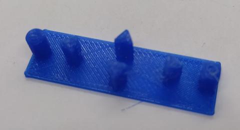 |
Image 6: Buttons from the 3D printer
Finally, there are two spacers that are to be inserted between Shield and the display to prevent the display from tensioning when screwing.
 |
Figure 7: LCD Keypad Shield, installation of the spacers
Links to download the 3D print files:
Housing lower part, Lid, Buttons, Spacer piece 1, Spacer piece 2
assembly
The LCD Keypad Shield also has free soldering points that are connected to the pen strips in addition to the pin strips that are used for the connection to the ESP32 D1 R32 board. We use these to connect the external modules to the board. To do this, we also have to stock them with pen strips.
 |
Likewise, the 3.9 KOHM should not be forgotten.
We start the assembly with the buttons. You are inserted into the corresponding recesses in the housing. The two potentiometers with a connection cable follow. For the connection cables, we halve a 3-pin jumper wire cable and solder it with the potentiometers. A strain relief with a cable tie is an advantage.
 |
 |
A 2-pin jumper wire cable is also halved and soldered with the BNC socket.
If the two potentiometers and the BNC socket are installed, the LCD keypad shield can be attached in the housing with four screws. Don't forget to insert the two distant pieces between the display and the board. The voltage converter module and the amplifier module can also be attached with four screws.
 |
The cables can now be inserted according to the wiring plan.
 |
Finally, the ESP32 D1 R32 board is plugged into the LCD keypad shield.
 |
Figure 13: Shared housing with the complete structure
Now on top of the lid, and assemble buttons for the potentiometers, then our functional generator is ready for use. We can use a USB charger or a power supply with 6 to 12 V for the power supply.
 |
Figure 14: Finished function generator on the oscilloscope
Good luck in the replica.


9 Reacties
Christian Magg
Ein anspruchsvolles Projekt, das ist mir klar, aber ich komme über diese Fehlermeldung: “CONFLICT! driver_ng is not allowed to be used with the legacy driver” einfach nicht hinaus. Nach meinen Recherchen liegt das an dem i2s.h driver. Der scheint die alte Version zu sein, aber wenn ich die 3 notwendigen neuen einbaue (i2s_std, i2s_pdm und i2s_tdm) bekomme ich das Programm nicht mehr kompiliert. Ich wäre jetzt wirklich für jede Hilfe dankbar. Im Voraus schon mal vielen Dank!
Andreas Wolter
@lorenz: ich vermute, dass es eine Änderung im ESP Core gab. Die Methode ledcDetachPin() gehört zur LED Control (LEDC) Library und ist für PWM Steuerung gedacht. Es scheint, als hätte man an der Stelle Änderungen vorgenommen. Ich würde zuerst versuchen, sie umzubenennen in ‘ledcDetach’
Infos dazu hier: https://espressif-docs.readthedocs-hosted.com/projects/arduino-esp32/en/latest/api/ledc.html
Es könnte auch helfen, auf eine ältere Version der Bibliotheken zurückzugehen. Das ist leider ein sehr häufig auftretendes Problem bei der Verwendung der ESP Bibliotheken.
Grüße,
Andreas Wolter
AZ-Delivery Blog
lorenz
Hallo,
ich habe den Fehler.
‘ledcDetachPin’ was not declared in this scope
Wie kann ich das ändern?
Gruß Lorenz
Andreas Wolter
@Bastlersiggi: wahrscheinlich wurde die Bibliothek verändert. Es gibt die Funktion i2s_write(). Damit könnte es wieder funktionieren. Oder zur älteren Version zurückkehren.
https://github.com/earlephilhower/ESP8266Audio/issues/273
Mit freundlichen Grüßen,
Andreas Wolter
AZ-Delivery Blog
Bastlersiggi
Der obige Sketch ergibt bei mir folgende Fehlermeldung:
FunktionsgeneratorESP32.ino:
In function ‘double triangleSetFrequency(double, uint8_t)’:
146:2: error: ‘i2s_write_bytes’ was not declared in this scope
i2s_write_bytes((i2s_port_t)0, (const char )&buf, size8, 100);
^~~~~~~~~~~~~~~
i2s_write_expand
exit status 1
Compilation error: ‘i2s_write_bytes’ was not declared in this scope
Verwendete IDE: 2.3.2 Board: ESP32 WROOM
Welchen Code kann man stattdessen verwenden bzw. den Sketch aktualisieren?
Gerald Lechner
Hallo Claus, GPIO12 ist schon richtig. Es ist nicht GPIO02 gemeint. Der Pin GPIO12 dient beim ESP32 dazu, die Versorgungsspannung für den Flash-Speicher zu steuern. Ist GPIO12 beim Bootvorgang auf High, beträgt die Versorgungsspannung 1.8 V, bei LOW 3.3V. Daher muss GPIO12 beim Booten auf LOW sein.
Das mit dem Widerstand ist richtig. Beim ESP32 Board könnte er weggelassen werden. Ich habe ihn auf das Display gelötet, da ich dieses auch mit der ESP8266 Version genutzt habe. Bei diesem Board ist dieser Anschluss mit A0 verbunden. A0 ist aber ein hochohmiger Eingang, der dann mit 5V beschädigt würde. Mit dem 3.9 kOhm Widerstand ist man auf der sicheren Seite und es funktionieren die Tasten trotzdem problemlos. Der Funktionsgenerator funktioniert natürlich nur mit dem ESP32!
Claus Teubner
Hallo,
wie immer, sehr schöner Artikel.
Heute habe ich den versteckten Tipfehler :-) gefunden.
‘…Ein weiteres Problem haben wir mit dem GPIO12 Anschluss. Der muss während des Bootvorgangs auf 0V liegen…’
Sollte doch GPIO2 statt GPIO12 Anschluss sein.
Außerdem sollte doch der 3,9kOhm Widerstand direkt am ESP32 reichen, dann bleibt das Display unverändert und wenn beides zusammengesteckt ist, ist sichergestellt, dass nur max. 3,3V am ESP anliegen. Falls die 3,9kOhm zum booten nicht reicht, tut es auch der 1kOhm alleine, dann sind die Taster-Spannungen etwas größer.
Bernd Albrecht
@Sven: Der D1 R32 ist “baulich” am Uno angelehnt. Die Uno Shields können also aufgesteckt werden. Aber es gibt deutliche Unterschiede bei der Pinbelegung, der gravierendste ist die zulässige Spannung von 3,3V beim D1 R32. Um das LCD Keypad Shield zu verwenden, müssen deshalb wie beschrieben die zusätzlichen Widerstände angelötet werden.
Sven Waibel
Hallo,
wieso steht beim LCD, den ihr verlinkt habt, dass dieser nicht mit dem D1 R32 kompatibel ist?
Grüße
Sven