
You probably know industrial robots that carry pre -made movements and are fixed at one point. What happens if we want to construct a robot that should move away from his place? There are other problems that need to be solved.
In this project we will build a four -legged, movable robot and show that there are no limits to the imagination. Everything is a question of persistence and the search for a way to put ideas into reality.

We want to show the basis of the construction and programming of the movements. Then it is a question of imagination, how we expand the movements and which additional modules we can install to improve this robot.
This article is divided into two parts. In part 1 we will assemble the robot and carry out the first movements. In part 2 we will send commands via infrared remote control, add an obstacle detection and a power supply with batteries to let the robot move freely.
Required hardware components
|
12 |
|
|
|
1 |
|
|
|
1 |
||
|
1 |
||
|
1 |
||
|
1 |
||
|
1 |
IR remote control |
|
|
various |
Required materials
Required software and sketches
- Arduino IDE
- I2c library (wire.h, integrated)
- PCA9685 Library (Adafruit_pwmservodriver.h)
- Ir remote control library (Irremote.h)
- Ultrasonics Sensor Library (SR04.H)
- quadruped_robot_home.ino
- quadruped_robot_pushups.ino
- quadruped_robot_shoulder.ino
- quadruped_robot_walk.ino
circuit diagram

Construction and assembly
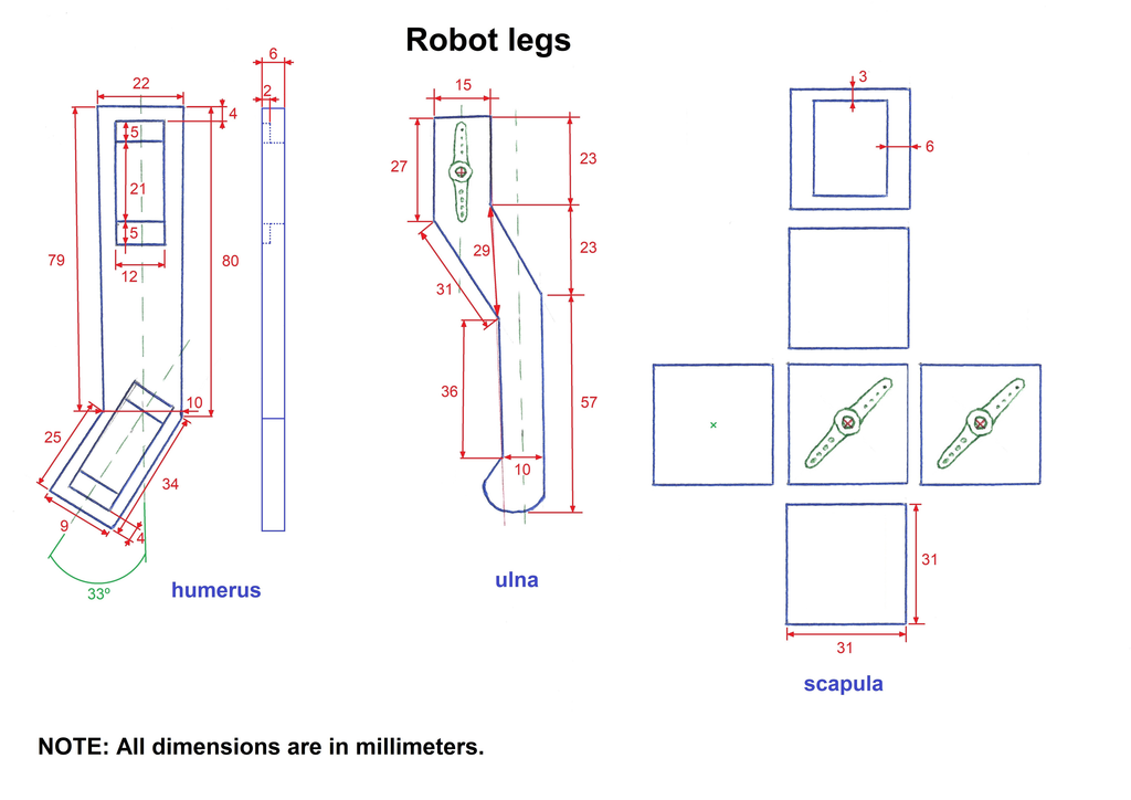
We will use 3 mm thick balsa wood for the skeleton of our robot. It has a low weight and it is easier to make changes to the parts. Below you will find the plans of the parts with their dimensions.


Before we start assembling the robot, we have to set all servomotors to 90 degrees, as this is the center of their movement. All parts are assembled in this middle. In this way we have a first visual reference of the condition of the legs and it will be easier to make the settings of the servomotors to determine the values of the robot's starting position, which we in the sketch Home.ino will be programmed.
We start with the shoulder blade. These parts are a cube of 31 mm edge length. One of the sides of the cube is uncovered, this is the side that is positioned towards the inside of the body. The upper and the lower side have a wall thickness of 3 mm, while the two sides are 6 mm thick with the parts that are screwed to the servootor shaft. The area that contains the axis of rotation of the robot body is also 6 mm thick. Before we attach the parts of the servo engine, we will look at our shoulder blades on the body. We want to ensure that we correctly assemble it, as the outer surface of each shoulder blade must contain the part that is screwed to every upper part of the leg.


The piece of the lower part of the leg has a thickness of 6 mm, in the upper part we will install the part that is screwed to the shaft of the servomotor. In the lower part of the leg, we will glue some rubber stones in to stop on the floor. Here it is also necessary to pay attention to the installation of the connecting piece to the servo motor, since it is installed in the lower leg part on the right side in one side and in which on the left side is installed in the opposite side.
The upper part of the leg also has a thickness of 6 mm. We have to cut a recess in order to insert the servo motor. We have to be careful, because the top on the right side has the recess on one side and the two on the left side on the opposite side. The upper servo engine operates the top, while the lower servo motor operates the lower part of each leg.


The body of the robot is a bit more complicated because we have to install four servomotors, on the axis of which the hub of the shoulder blade is screwed. On the opposite side of the servo engine that moves the shoulder blade, we have to insert a wave from the hub to the hole in the body holder, which must match the servomotor shaft so that the shoulder blade moves smoothly. The wave must have a suitable thickness so that it cannot be deformed by the movement and the weight of the robot can carry. In our prototype, this shaft has a thickness of 6 mm.
After all parts are built, we start assembling the robot. First we will install two servo motors in each top and the four servomotors into the body of the robot. As soon as we have installed all servo motors, we have to install each leg into the appropriate shoulder joint. We previously made a default of all servomotors to 90 degrees. With these positions we have to assemble the hub on the body by placing it on the shaft of the servomotor so that it fully matches the body. We screw the hub onto the shaft of the servo motor and then we use the shaft by leading it through the body support and to the hub. This procedure is carried out for the four shoulder blades of our robot.


After assembling the mechanical parts of the robot, we install the cover of the body and then the PCA9685 card including AZ-ATMEGA328 microcontroller with the Shield. With the prototype Shield you are also able to expand your project according to your needs. You can already see the installed IR receiver module here that we will use in Part 2.


We make all the connections of the module and the servomotors, as shown in the electronic circuit diagram. Then we start programming.
Functioning and programming the sketch
As actuators for the movements, we use 12 MG90S service engines, the gears of which are made of metal and thereby have better mechanical resistance. To control the engines, we use the "PCA9685 16 Channel 12 Bit PwM Servo Driver" module, which has two important functions: firstly, the supply of the servomotors with 5 VDC from an external power supply and secondly the control of each servomotor via the corresponding PWM pin with The data transmitted by the microcontroller via the I2C port. Only two pins are used for communication between the microcontroller and the PCA9685 module, which remains space for later extensions.
In the sketch we determine the position that every servomotor has to take. The combined rotations of the engines lead to the movement sequence of the robot. The microcontroller sends the respective positions of the servos to the motor driver module via the i2C interface.
A tedious part of this project is to set the values for each position of the servomotors of each leg for the coordinated movement sequence and thus run the robot. In this part 1 of the project I show three sketches with some basic movements and another sketch with the starting position of the robot.
In order to provide the robot components with excitement in this part 1 of the project, we use a fixed 5 VDC source. Since the microcontroller remains connected to the Arduino IDE via the USB interface, it receives its tension.
In part 2 of the article we will add the HC-SR04 ultrasonic sensor, which measures the distance to each obstacle in front of the robot. We will also use the IR receiver module and an IR station remote control to issue commands and finally we will install batteries for the power supply so that the robot can move freely.
Description of the sketch quadruped_robot_home.ino
This is the initial position of the robot. As you can see, the code of this first sketch is very simple and only performs the initial positioning movement of the servomotors. The first two lines of the code are the libraries that we need to correctly carry out the sketch. Wire.h Is the library for I2C communication and Adafruit_pwmservodriver.h is necessary for the use of the PCA9685 module.
#include <Wire.H>
#include <Adafruit_pwmservodriver.H>
The next three lines are the implementation of one Adafruit_pwmservodriver-Objekt to control the servomotor positions and the variables Servomin and Servomaxthat represent the values of the rising and falling flank for the 0 degree or 180 degree positions of the servomotors.
Adafruit_pwmservodriver Servodriver_Module = Adafruit_pwmservodriver();

#define Servomin  100
#define Servomax  500
In the set up()-We first initialize the serial monitor and in the next line the PCA9685 module through its previously implemented object. With the function Begin () Let us give the work frequency of the servomotors with the call Setpwmfreq (50) on, the 50Hz is. In the last line we call the Home ()-Function on.
void set up() {
      Serial.Begin(9600);
      Servodriver_Module.Begin();
      Servodriver_Module.Setpwmfreq(50);
      home();
}
We analyze the first line of the function Home (). The first servomotor that will change its position is that with the number 0, which belongs to the lower part of the left front. With the call SetPWM (0, 0, 420) the object Servodriver_Module Let us indicate the PCA9685 module that it moves the servomotor connected to its port 0 and should bring it into the position, which results from the subtraction of the value of the rising flank (0) from the falling flank (420).
void home() {
      Servodriver_Module.setpwm(0, 0, 420);
      Servodriver_Module.setpwm(1, 0, 360);
      Servodriver_Module.setpwm(2, 0, 350);
      Servodriver_Module.setpwm(4, 0, 400);
      Servodriver_Module.setpwm(5, 0, 440);
      Servodriver_Module.setpwm(6, 0, 280);
      Servodriver_Module.setpwm(8, 0, 240);
      Servodriver_Module.setpwm(9, 0, 220);
      Servodriver_Module.setpwm(10, 0, 340);
      Servodriver_Module.setpwm(12, 0, 190);
      Servodriver_Module.setpwm(13, 0, 260);
      Servodriver_Module.setpwm(14, 0, 260);
      delay(10000);
}
The subsequent lines move the other engines according to the same principle. The source code describes which engine is responsible for which "body part".
In this sketch it remains Loop ()-Function empty, since only the starting positions when calling the set up()-Function and thus when the microcontroller starts.
Download quadruped_robot_home.ino
Description of the sketch quadruped_robot_pushups.ino
With this sketch, the robot is triggered a few small movements by the engines on the lower and upper leg parts. In the Loop () Will now Pushups () called. As a result, the robot moves up and down again and again.
The 12 servomotors change their position and then return to the starting position of Home () back. The code lines are similar to those we have already seen. The function servoDriver_Module.SetPWM () As a parameter, has the number of the servomotor to be moved and the new position.
Download quadruped_robot_pushups.ino
The following graphic shows how the movements of the leg parts work depending on the change in the position of the servomotors.

Description of the sketch quadruped_robot_shoulder.ino
With this sketch, movements in the servo motors of the shoulder blades of the robot are carried out. The code lines are very similar again. Of the Loop () From this time we continuously call the Shoulder ()-Function on. It leads a movement of the Home ()Positions of the shoulder surmotors to the new positions. Here, too, these positions are with the call servoDriver_Module.SetPWM () specified.
Download quadruped_robot_shoulder.ino
Description of the sketch quadruped_robot_walk.ino
The last sketch in this first part enables the robot to run. To do this, a sequence must be programmed, which on the one hand carries out the right movements of the legs and, on the other hand, ensures that the robot's balance.
The first difference to the other sketches is the variable declaration called Int movement_speed With a value of 50. This is used to take a break of 50 microseconds between the movements of the servomotors.
intimately movement_speed = 50;
Of the Loop () From we continuously call the walk()-Function that sends the movement commands to the servomotors via the PCA9685 module. With servoDriver_Module.SetPWM () the required parameters are also handed over here. Based on the diagram inserted above, you can better assign the values to the movements.
We start in the starting position Home (), in the set up() is called. Then we take a step forward with the left front leg. To do this, we have to lift the lower leg with the servo engine 0, move the upper part with the servo engine 1 forward and lower the lower part with the servo engine 0 to cut the leg on the floor.
Servodriver_Module.setpwm(0, 0, 450);
delay(movement_speed);
Servodriver_Module.setpwm(1, 0, 330);
delay(movement_speed);
Servodriver_Module.setpwm(0, 0, 420);
delay(movement_speed);
The next leg, which has to take a step forward, is the right hind leg so that the robot can keep your balance. To do this, we carry out the same movements as the previous leg. Servomotor 8 is raised, servo engine 9 moves forward and servo engine 8 lowered.
Servodriver_Module.setpwm(8, 0, 210);
delay(movement_speed);
Servodriver_Module.setpwm(9, 0, 250);
delay(movement_speed);
Servodriver_Module.setpwm(8, 0, 240);
delay(movement_speed);
The next action is to move the robot's body forward. Here only the servos are moved in the shoulders. They are moved back, which means that the robot's body moves forward while the legs rest on the floor.
Servodriver_Module.setpwm(13, 0, 230);
Servodriver_Module.setpwm(1, 0, 360);
Servodriver_Module.setpwm(5, 0, 470);
Servodriver_Module.setpwm(9, 0, 220);
delay(movement_speed);
Now we have to move the other two legs, the left hind leg and the right front leg. We start with the right front leg. The movements are the same as the two previous ones. We lift with servomotor 12, we push with servomotor 13 and we lower with servomotor 12.
Servodriver_Module.setpwm(12, 0, 140);
delay(movement_speed);
Servodriver_Module.setpwm(13, 0, 260);
delay(movement_speed);
Servodriver_Module.setpwm(12, 0, 190);
delay(movement_speed);
Now the left hind leg. Lift with servomotor 4, pushing with servomotor 5 and lowering with servomotor 4. There is a break of 50 ms between all movements.
Servodriver_Module.setpwm(4, 0, 450);
delay(movement_speed);
Servodriver_Module.setpwm(5, 0, 440);
delay(movement_speed);
Servodriver_Module.setpwm(4, 0, 400);
delay(movement_speed);
At the end of this movement sequence, the engines return to their home () position. Due to the recurring call from Walk () in the Loop (), the robot moves permanently.
All of this serves as a basis to be able to move the robot as desired.
If you don't see a video or cannot play it at this point, please change the cookie settings of your browser.


2 commentaires
TheMediumIsPizza
Tolles Projekt! Muss ich unbedingt mal nachbauen … Euch fehlt aber definitiv jemand mit einem 3D-Drucker ;)
Michael
Hallo Miguel, ein schönes Projekt! ;-)