In the warm summer months, darkening the room is essential. In addition, a time-switched blackout can also improve the sleep rhythm and quality.
In this blog post, we want to build a retrofittable darkening system with the help of a microcontroller.
Hardware
In addition to soldering equipment, the implementation also requires a 3D printer is required!
If you do not have access to a printer, you can also order the required parts from 3D printing service providers online.
You will need the following components for the complete implementation:
Stepper motor driver (A4988 or DRV8825)
Power supply 12V (min. 1A)
Step down module (LM2596S)
For the test setup we recommend the
If not already available, you will also need
The width and length of the roller shutter should be selected so that it can be mounted on the wall above the window so that the motor can also be attached to the wall.
Most blackout blinds are supplied with a chain to open or close the shutter.
As the torque of the motor is not sufficient to move the chain, the motor is attached directly to the axis of the blind using a suitable attachment instead of the original parts.
The following f3d files can be edited and exported in the CAD program Fusion 360 from Autodesk.
The software is free for private users.
With this mounting option, it is now possible to move the roller shutter with the motor. However, the problem is that as soon as the motor is no longer supplied with power, the roller is no longer held in position and unrolls completely.
However, permanently blocking the motor would result in increased and unnecessary power consumption.
For this reason, teeth are added to the wheel on the motor side so that it can be locked and held in position by the servomotor.
Print out the following files with the 3D printer:
If you need other dimensions, you can download the f3d files for editing here:
Once you have printed out all the components, it's time to assemble them.
Glue the ServoLock to the plastic arm supplied with the servo. (Superglue or two-component adhesive recommended)
The servo motor and the stepper motor can now be attached to the bracket using the screws. (Stepper motor with M3 threaded screws; servo with the enclosed screws)
Before attaching the ServoLock to the servo, set the servo angle in the program to 0° and attach the lock to the servo perpendicular to the stepper motor axis and screw it tight.

Figure 1: Stepper motor with servo motor in 0° position
The ball bearing can simply be inserted into the holder and fixed with adhesive as required.

Figure 2: Bearing on the other side
For mounting on the wall, the stepper motor must be removed again as it covers the fastening options.
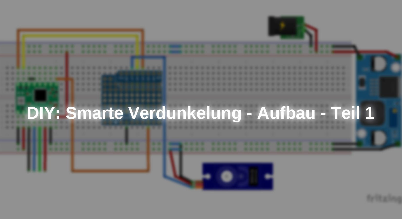
Build the following circuit on the breadboard:

Figure 3: Circuit diagram of the test setup
Note: The microcontroller does not have to be plugged in, the cables can also be plugged into the socket strips.
|
Motor driver |
Servo motor |
||
|
GND |
GND |
Red |
5V |
|
VDD |
5V |
Orange |
GPIO 23 (D7) |
|
1A |
Stepper motor blue |
black |
GND |
|
1B |
Stepper motor black |
LM2596S |
|
|
2A |
Stepper motor green |
IN+ |
12V |
|
2B |
Stepper motor red |
OUT+ |
5V |
|
VMOT |
12V |
IN- / OUT- |
GND |
|
DIRECTION |
GPIO 18 (D5) |
Push button |
|
|
STEP |
GPIO 19 (D6) |
Contact 1 |
GND |
|
ENABLE |
GPIO22 (D1) |
Contact 2 |
GPIO 21 (D2) |
|
SLEEP |
RESET |
|
|
Table 1: Connections of the components (GPIO labeling to ESP32)
Before you supply the circuit with voltagecheck the output voltage (5V) of the voltage converter!
To protect the motor from excessive currents, the current limitation can be regulated using the small potentiometer on the driver. In order not to overload the motors, a maximum current of 1A should be applied to the motor. The reference voltage, which can be measured on the metal ring of the potentiometer, corresponds to half of the maximum current, i.e. in our setup you have to turn the potentiometer until you measure 0.5V against ground on the metal ring of the potentiometer.
Software
Once you have connected all the components correctly, we can take care of the software.
If you are programming an ESP32 in the Arduino IDE for the first time, copy the following link in the Arduino IDE under:
File->Preferences->Additional boards manager URLs : https://dl.espressif.com/dl/package_esp32_index.json
and install the ESP32 package in the board manager.
The driver (CP2102) for this board is already installed by the operating system.
The motor can be controlled via two pins on the motor driver. On the one hand, the DIR pin can be used to set the direction of rotation of the motor and the STEP pin can be used to rotate the motor by one step by sending a pulse.
The following program controls the motor so that it rotates two revolutions in both directions:
|
#define dirPin 18 |
In the code, the individual steps are executed by a for loop for the correct number of steps. The speed can be adjusted using the pauses between the pulse edges.
This program is completely sufficient for the first attempts, but for the final drive of the roller shutter there are better alternatives such as the use of a library.
Install the AccelStepper library. This is possible either via the integrated library management of the Arduino IDE, or via GitHub as a .zip file.
The following program closes and opens the dimming. The servo motor is used as an interlock to de-energize the motor via the ENABLE pin on the driver.
|
#include "Arduino.h" |
You can run the program here download the program.
At the beginning of the program, constants are defined and an object of the library class is created.
The setServoAngle() method controls the servo motor with a PWM signal, which is calculated from the target angle.
The PWM channel is started in setup() and the setup commands of the stepper motor are called.
The unroll() function moves the stepper motor until it has reached the target position.
In the loop() routine, the servo is opened first, then the stepper motor is moved to the target position and closed again at the end. The sequence is then repeated for the start position.
Before loading the program onto the microcontroller, adjust the number of motor revolutions and the direction.
The servomotor should also be set so that the arm is perpendicular to the motor axis of the stepper motor in the zero position.
Conclusion
Now that the dimming system has been fitted with a motor in this section so that it can be operated automatically, the next step is to implement the control system.
To do this, a web server is set up on the microcontroller, which can be used to control the roller shutter. In addition, a housing is provided for the microcontroller and the electronics to enable secure attachment to the wall.
Finally, MQTT and a button will be integrated so that the shutter can be fully integrated into a smart home system.
Have fun building it :)


3 commenti
Anstela
Hallo @Jonas,
Gute Neuigkeiten: Teil 2 des Projekts ist ab heute verfügbar! Der Link dazu: https://www.az-delivery.de/blogs/azdelivery-blog-fur-arduino-und-raspberry-pi/diy-smarte-verdunkelung-steuerung-teil-2
Herzlichen Dank für die Geduld und das Interesse am Projekt.
Grüße, Anstela AZ-Delivery Blog
Tom
Coole Sache, werde ich in den nächsten Tagen mal nachbauen. Wann wird PART 2 des Projektes vorgestellt?
Jonas
Coole Idee. Gibt es auch Überlegungen zur Stromversorgung (netzunabhängig)? Nich an jedem Fenster hat man in der Regel die Möglichkeit auf Netzstrom zuzugreifen.