In the last part, the hardware, and in particular the motor to move the blind, was installed.
However, the control of the motor and especially the automation still leaves a lot to be desired.
In this part, the blackout is to be closed or opened automatically at the set time.
Hardware
In addition to the hardware from the test setup in the last section, you will also need
Threaded screws (M3)
PCB spacer (M2)
Fusible thread (M2 & M3)
In order to be able to operate the assembly in the long term, it is recommended to mount it on a breadboard:

Figure 1: Wiring on the breadboard
PCB size: 3 x 7 cm
Before applying power to the circuit, check that all connections are correct, especially the power supply for short circuits or reversed wires.
|
D1 mini (GPIO) |
|
|
A4988DIR |
22 |
|
A4988STEP |
21 |
|
A4988ENABLE |
18 |
|
Servo: Orange |
23 |
|
Button |
17 |
Table 1: Connection overview
Note: Due to the layout on the board, some GPIOs have changed.
Software
1 push-button control
The push-button is used to close or open the shading. The code from the last section can easily be added for this purpose.
#include "Arduino.h" #include <AccelStepper.h> #define dirPin 22 #define stepPin 21 #define stepsPerRevolution 200 //1.8° #define servoPin 23 #define enablePin 18 #define buttonPin 17 const int pwmChannelServo = 0; AccelStepper stepper = AccelStepper(AccelStepper::FULL2WIRE, dirPin, stepPin); const int numberOfTurns = -15; long targetPosition = stepsPerRevolution * numberOfTurns; void setServoAngle(int angle) { // Min Duty: ca. 1638 (0.5ms), Max Duty: ca. 8192 (2.5ms) bei 16 Bit int dutyMin = 1638; int dutyMax = 8192; int duty = map(angle, 0, 180, dutyMin, dutyMax); ledcWrite(pwmChannelServo, duty); } void setup() { Serial.begin(115200); ledcSetup(pwmChannelServo, 50, 16); ledcAttachPin(servoPin, pwmChannelServo); stepper.setMaxSpeed(500); stepper.setAcceleration(300); stepper.moveTo(0); pinMode(enablePin, OUTPUT); pinMode(buttonPin, INPUT_PULLUP); } void abrollen(long pos) { digitalWrite(22, LOW);//enable Motor setServoAngle(0); stepper.moveTo(pos); while (stepper.distanceToGo() != 0) { stepper.run(); } setServoAngle(80); digitalWrite(22, HIGH);//disable Motor } void loop() { if(!digitalRead(buttonPin)) { if (stepper.currentPosition() == targetPosition) { Serial.println("öffnen"); abrollen(0); // öffnen } else if (stepper.currentPosition() == 0) { Serial.println("schließen"); abrollen(targetPosition); // schließen } } } |
You can use the code here download.
The basic structure of the program has not changed compared to the first part.
Only the position of the motor is queried in the loop and the corresponding target position is controlled accordingly.
The motor sequence, such as controlling the servomotor, is now analogous to the unwinding method.
2 Time control
To retrieve the current time via the Internet, the connection to a NTP server is required. An external library is required to make reading out the time as easy as possible.
You can download this via the following link from GitHub as a .zip and can be downloaded in the Arduino IDE under
Sketch > include Library > Add .zip Library ...
and installed.
Alternatively, you can use the NTPClient library via the integrated library management.
The following method regulates the algorithm for time control:
(The following code is for explanatory purposes only, the entire program with all variables can be downloaded via the link).
void timeControl() { timeClient.update(); //(1) /*Serial.print(timeClient.getHours()); Serial.print(":"); Serial.println(timeClient.getMinutes()); */ if(timeClient.getHours() == tOpen.tm_hour && timeClient.getMinutes() == |
At the start of the method, the time is first updated via the NTP server(1). This is followed by a comparison of the current time with the times set in the setup (2). If there is a match here, the value of timeControlTriggered is queried (3), which prevents permanent repetition during the same time, and the motor position is adjusted. (4), The command is only executed if it is not yet at the target position.
If the times do not match, the value of timeControlTriggered is set to false (5).
For troubleshooting purposes, the time can be displayed in the top lines, which can be used to identify problems with the time zone, for example.
The required variables and objects can be found in the final program, which here can be downloaded here. In this program, the button query is also located in a separate method in order to improve the clarity of the program.
Housing
A housing is required in order to be able to mount the finished circuit on the wall.
For example, this can be downloaded and printed out here:
(.stl)
If you require other dimensions, you can also find the f3d files here, which can be edited in the CAD program Fusion 360:
(.f3d)
After the housing is printed, you can press the fusible threads into the plastic with a hot soldering iron.
You will need the screws (M2) from the spacer set to secure the circuit board in the housing.
Screw the voltage converter and the cover in place with M3 screws.

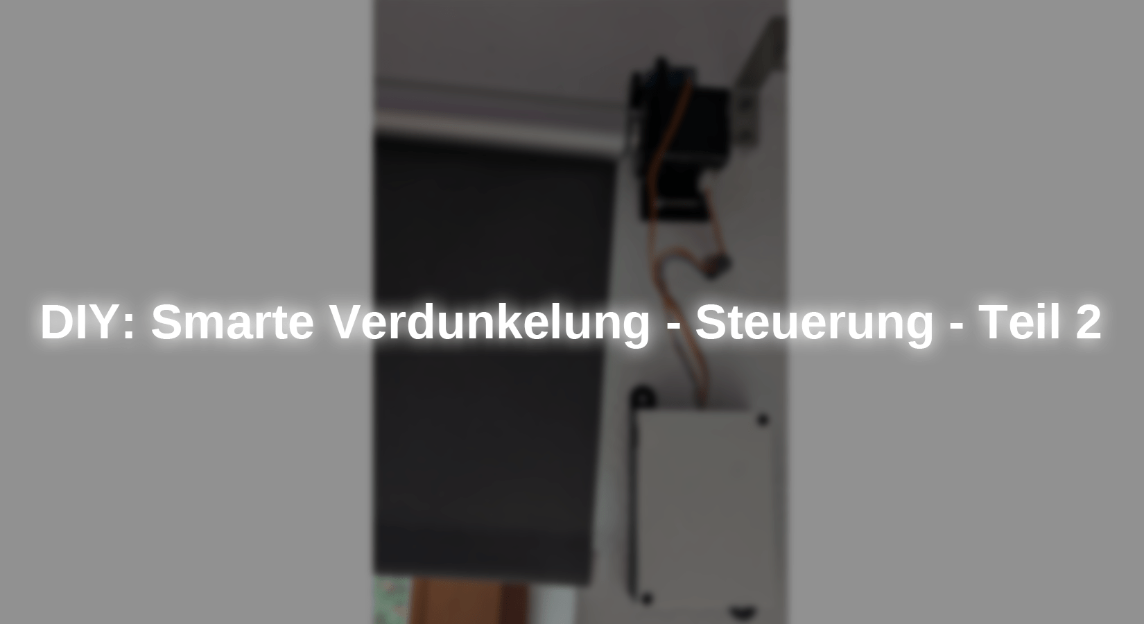
Figure 2: Completed assembly with housing
Conclusion
As the darkening system can now be controlled after this part and the first automation in the form of a time control has already been installed, the darkening system is already fully functional.
However, as announced in the last part, the darkening system should also be Smart Home compatible, so the web server and the MQTT connection will be added in the next part.
Have fun building it :)


