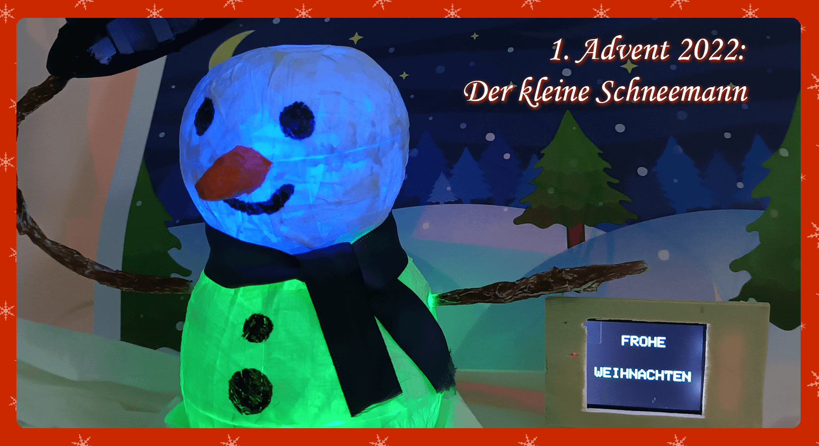
The little snowman
The end of the year is getting closer and closer and so is Christmas. We decorate with Christmas motifs. Why do not we greet there with nice figures that wish us a happy holiday!!!
With this project we will build a snowman that greets us at Christmas in several languages, whose body lights up and who makes movements with his arm. For this we need a WS2812B RGB LED ring with 50 mm and another one with 37 mm diameter. Also an SG90 or MG90S servo motor, a 1.8-inch SPI TFT screen with 128 x 160 pixels, an MB102 breadboard kit and to control all these elements an ATmega328 microcontroller.
Materials needed
|
1 |
AZDelivery ATmega328 microcontroller board with USB cable alternatively: Nano V3.0 Atmega328 with USB cable or |
|
1 |
|
|
1 |
|
|
1 |
|
|
1 |
|
|
1 |
|
|
1 |
|
|
1 |
|
|
|
|
|
|
|
|
|
|
|
1 each |
Ball shape 6.5 cm and 8.5 cm |
|
1 |
Required software
- Arduino DIE
- cute_little_snowman.ino
- TFT.h library (via library management)
- SPI.h library (integrated)
- SD.h library
- Adafruit_NeoPixel.h library (via library management)
- Servo.h library (integrated)
- AZ logo as BMP
Circuit

Instead of the Uno microcontroller with ATmega328 you can also use the Nano with ATMega328 or Mega with ATmega2560 use!
Tinker snowman
We will make a snowman out of kitchen paper and white glue. The white glue is diluted with water. We take two ball shapes of 8.5 cm for the body and 6.5 cm for the head, cover them with pieces of paper and apply a little of the solution of white glue and water with a brush. We add several layers of this so that together they are thick enough for us to work on later and let them dry. When they are dry, we make a cut in the circumference of the spheres to remove the inner molds and install the LED rings inside. Also, the servo motor that drives the movement of the arm. We also make a hole in it to be able to pass the connection cables to the microcontroller.


For the hat we use white cardboard. The later color and shape are up to the reader. As you can see in the photos, the 2mm metal wire is attached to the servo motor and comes out through a hole in the side of the body ball. It will serve as the pivot point of the arm. At the end of the arm we glue the hat. When we have everything installed inside, we glue the two parts of the balls together and cut a hole in the upper part of the body ball. There we apply the head ball. Finally, we apply the scarf and the nose, which we also made using the same method as the spheres. Finally, we can still paint it, for example, orange.
The two LED rings are used to light up the inside of the body and the head of our snowman. With the servo motor, we move the arm. This one holds the hat and its movement makes us greet. The TFT screen displays the greeting messages in several languages.
Important note: In order to use the SD card reader with TFT screen, four pins must be soldered on. We do this because we want to use the AZ-Delivery-logo will be shown. To display the images downloaded from the card reader on the screen, the image must have a resolution of 160 x 128 pixels, be in landscape format and be the file type BMP - 24 bit bitmap.


Program flow and sketch
The program starts with the initialization of the LED rings and the servo motor. The SD card reader is initialized by checking if a card is inserted. If there is an error, the execution of the program is stopped. If the initialization is successful, the TFT screen is initialized.
Once all modules are initialized, the image of the logo is downloaded from the SD card and displayed on the screen. The snowman greets us by removing her hat and the logo appears with the first message. After this first message, the doll's body lights up, the first greeting appears in one language and the doll's head lights up, followed by the greeting in another language. The color of the puppet's body changes and it makes another greeting. Then the color of the head lighting changes. The color of the body and head change until the last message, then the LEDs on the body and head turn off, pause and start again.
Let's start with the analysis of the sketch. The first thing we need to do, as with all projects, is to include the necessary libraries to later implement the functions and methods we need to work with the LED rings, the 1.8-inch TFT screen, the screen's SD card reader, and the arm's servo motor.
#include <Adafruit_NeoPixel.h>

#include <SPI.h>
#include <SD.h>
#include <TFT.h>

#include <Servo.h>
Next we will implement an object of the TFT screen. As arguments of this implementation we have to enter the pins of the connection to the microcontroller of its control and access pins. These are the pin lcd_sc (signal to indicate that information is being sent to it), dc (send data) and rst (reset the screen). For these three lines we have to define to which pins of the microcontroller we connected them. In addition, we also need to define the connection pin of the line for using the SD card reader, which is sd_cs.
#define sd_cs 4
#define lcd_cs 10
#define dc 9
#define rst 8
TFT TFTscreen = TFT(lcd_cs, dc, rst);
To make the code more readable, we define a constant with the pin number of the microcontroller we connected each LED ring to and the number of LEDs (12) each ring has.
#define big_ring_LED 7
#define big_ring_LED_count 12
#define small_ring_LED 6
#define small_ring_LED_count 12
To use the LED rings, we need to instantiate an object for each of them, just like for the TFT screen. As arguments we have to enter the number of LEDs of the respective ring (big_ring_LED_count and small_ring_LED_count). Also the pins of the microcontroller to which each one is connected (big_ring_LED and small_ring_LED). In addition, the properties of the ring (three-color LEDs; NEO_GRB) and the working frequency of 800 KHz (NEO_KHZ800).
Adafruit_NeoPixel big_ring(big_ring_LED_count, , NEO_GRB + NEO_KHZ800);
Adafruit_NeoPixel small_ring(small_ring_LED_count, small_ring_LED, NEO_GRB + NEO_KHZ800);
We also create an object for the servo motor.
Servo servo_arm;
To specify the color we want to shine, we configure the luminosity value that each LED (red, green and blue) emits with a maximum value of 150. The function for this is ring_name.Color(150,0,0), where we specify the object (name of the ring), the name of the color and the luminance value of each LED (R, G, B). For example, to make the red color shine the red LED gets a value of 150 and the other two 0, so "off". To make the programming work easier, we define some variables with the initials of the LED ring (b for big and s for small) and the color. This way we only need to specify the name of the color, we avoid possible errors and following up the sketch is easier. The definitions of the variables and the assignment of the colors are:
// Definition of the colors variables' names for WS2812B big ring
uint32_t b_red = big_ring.Color(150,0,0);
uint32_t b_green = big_ring.Color(0,150,0);
uint32_t b_blue = big_ring.Color(0,0,150);
uint32_t b_yellow = big_ring.Color(150,150,0);
uint32_t b_purple = big_ring.Color(150,0,150);
uint32_t b_light_blue = big_ring.Color(0,150,150);
uint32_t b_white = big_ring.Color(150,150,150);

// Definition of the colors variables' names for WS2812B small ring
uint32_t s_red = small_ring.Color(150,0,0);
uint32_t s_green = small_ring.Color(0,150,0);
uint32_t s_blue = small_ring.Color(0,0,150);
uint32_t s_yellow = small_ring.Color(150,150,0);
uint32_t s_purple = small_ring.Color(150,0,150);
uint32_t s_light_blue = small_ring.Color(0,150,150);
uint32_t s_white = small_ring.Color(150,150,150);
To display a bitmap image from an SD card, an instance of the PImage-class must be used. So we create the instance named logo.
PImage logo;
The next step is now the implementation of the setup()-method to set the initial conditions when we apply power or initialize the microcontroller. We start with the initialization of the serial monitor to display information on the serial monitor.
Serial.begin(9600);
Next, we need to initialize the two LED rings. For this we write the object we declared for each ring type followed by the function call begin().
big_ring.begin();
small_ring.begin();
Then we declare the initial conditions of our servo motor. We specify with the function attach() we specify the pin of the microcontroller to which we have attached it (5). With the instruction write() we set the position in degrees where it will be initially positioned. In our case it is 90 degrees.
servo_arm.attach(5);
servo_arm.write(90);
The next module to initialize is the SD card reader on the TFT screen. First we display a message on the serial monitor saying that we are going to initialize the SD card reader. A simple condition is implemented to initialize the card reader. If the SD card reader is not initialized (!SD.begin), the program will print an error message and will not continue. On the other hand, if the reader is initialized correctly, the if statement will not be executed and the next line of the sketch will be executed, informing us in the Serial Monitor about the success of the initialization.
Serial.print(F("Initializing SD card..."));
if (!SD.begin(sd_cs)) {
  Serial.println(F("failed!"));
  return;
}
Serial.println(F("OK!"));
The next component we initialize is the TFT screen with the call begin() after the name of the object we created for the screen. With the statement background(0, 0, 0) we set the background of the screen to black.
TFTscreen.begin();
TFTscreen.background(0, 0, 0);
The last step is to load the BMP file from the SD card into the instance that we have created logo the PImage-class. We pass the name of the file as an argument to the statement to load the image with logo = TFTscreen.loadImage("az12.bmp"). In case the image cannot be loaded, a condition is implemented that gives us the information on the serial monitor.
logo = TFTscreen.loadImage("az12.bmp");
if (!logo.isValid()) {
  Serial.println(F("Error while loading arduino.bmp"));
}
This completes the implementation of the setup()-method is completed, and we start implementing the loop()-method.
With the first line of the loop()-method, we check if the format of the downloaded image is correct to display it on the screen. If the format is not correct, the sketch breaks with the return-statement.
if (logo.isValid() == false) {
              return;
      }
If the format of the bmp file is correct, the sketch will continue. First all LEDs in the rings are marked with clear() is switched off. With the show()-instruction is then used to transfer the command to the LED rings.
big_ring.clear();
big_ring.show();

small_ring.clear();
small_ring.show();
Now we need to display the downloaded image file on the TFT screen, for which we change the background of the screen with TFTscreen.background(0, 0, 0) to make it black. With the statement TFTscreen.image(logo, 0, 0) we draw on the screen the graphic of the logo starting with the pixel located at the coordinates X=0 and Y=0.
TFTscreen.background(0, 0, 0);

Serial.println(F("drawing image));
TFTscreen.image(logo, 0, 0);
Once the graphic is on the screen, the puppet kindly takes off its hat to say hello. The movement is done by the servo motor with the initial position of 90 degrees to the final position of 40 degrees in intervals of one step each and a small pause of half a second.
for (int pos=90; pos>40; pos -=1) {
  servo_arm.write(pos);
}

delay(500);
Then, without deleting the bmp file, we show below it the message "WISHES YOU", for which we change the text size with TFTscreen.setTextSize(3) to 3. The color of the text is set with TFTscreen.stroke(255, 40, 20) light blue. The three values of the argument are the values of the colors. With the following line we write the word WISHES to the coordinates X=30 and Y=45 and the word YOU to the coordinates X=55 and Y=80. We pause for half a second to read the text.
TFTscreen.setTextSize(3);
TFTscreen.stroke(255, 40, 20);
TFTscreen.text("WISHES", 30, 45);
TFTscreen.text("YOU", 55, 80);
delay(500);
Now we will light up the body of our snowman, for which we first switch off all LEDs, set the brightness to a value between 50 over 255 and define the LEDs that should light up.
A note: the ring has 12 LEDS, but the numbering for the operation starts with the number 0, which corresponds to the first LED, up to the number 11 of the last LED.
When we have configured all the LEDs with the desired color, we execute the instruction big_ring.show() statement. This executes all the previous lines so that our ring lights up.
big_ring.clear();      // Power off the large ring LEDs.
big_ring.setBrightness(50);         // Set Luminosity set to 50 out of 254
big_ring.setPixelColor(0, b_green); // We set the LED 1 of 12 of the ring lights green
big_ring.setPixelColor(2, b_green);                 // LED 3
big_ring.setPixelColor(4, b_green);                 // LED 5
big_ring.setPixelColor(6, b_green);                 // LED 7
big_ring.setPixelColor(8, b_green);                 // LED 9
big_ring.setPixelColor(10, b_green);                // LED 11
big_ring.show();
We are going to congratulate Christmas in different languages, so we need to change the messages that will appear on the screen. We will change the size, the color of the text and the message, so the first thing we will do is to change the screen background with the statement TFTscreen.background(0, 0, 0) to clear it. We configure the size of the text with the value 2, we configure the color in blue and the first word will be output at the coordinates X=20 and Y=20 and the second word at the coordinates X=30 and Y=70. These coordinates are for centering the words on the screen in Spanish. We pause for 3 seconds.
TFTscreen.background(0, 0, 0);
TFTscreen.setTextSize(2);
TFTscreen.stroke(150, 150, 0);
TFTscreen.text("FELIZ", 50, 20);
TFTscreen.text("NAVIDAD", 37, 70);
delay(3000);
After this message, we will light the head of our snowman. The instructions are similar to those for lighting the body.
small_ring.clear();
small_ring.setBrightness(50);
small_ring.setPixelColor(0, s_blue);
small_ring.setPixelColor(2, s_blue);
small_ring.setPixelColor(4, s_blue);
small_ring.setPixelColor(6, s_blue);
small_ring.setPixelColor(8, s_blue);
small_ring.setPixelColor(10, s_blue);
small_ring.show();
delay(1000);
We wrote greeting messages in different languages and varied the color of the body, as well as the head of our friendly snowman. You can insert as many messages as you want, change the color and also the number of lit LEDs by simply changing the values of the parameters in the instruction lines of each element. The coordinates must be changed so that the messages are centered in the different languages.
As soon as the last message is displayed on the TFT screen, after a waiting time of 3 seconds, the servo motor is activated and the hat is placed on the head of our snowman. This happens in a loop.
for (int pos=40; pos<90; pos +=1) {
          servo_arm.write(pos);
}
After the snowman puts on the hat, the message on the screen is deleted.
TFTscreen.background(0, 0, 0);
The last action is to turn off the LED rings, but we turn off each LED individually every half second.
small_ring.setBrightness(50);
small_ring.setPixelColor(0, s_black);
delay(500);
small_ring.show();
small_ring.setPixelColor(2, s_black);
delay(500);
small_ring.show();
small_ring.setPixelColor(4, s_black);
delay(500);
small_ring.show();
small_ring.setPixelColor(6, s_black);
delay(500);
small_ring.show();
small_ring.setPixelColor(8, s_black);
delay(500);
small_ring.show();
small_ring.setPixelColor(10, s_black);
delay(500);
small_ring.show();
delay(500);
After all LEDs have been switched off, the main loop starts again from the beginning after a short waiting time.
With this project we wish you a Merry Christmas, enjoy your free time. We are looking forward to your comments and suggestions.
Merry Christmas and thank you very much.


