This manual is also available as a PDF document available. Circuit and program are especially suitable for beginners.

Image 1: Shaking cube with individual LEDs
There are a lot of cube circuits in electronics. Discrete with ICs of the 74-series, or CMOS chips, with AVR controllers, PICs etc.. The representation of the number of dice usually happens with seven LEDs. With discrete circuits, a ring counter counts through six states so fast that the eye and brain cannot follow the display. The six codes from 0x00 to 0x05 have to be recoded for the display with the seven LEDs. This requires a truth table and a bunch of logic gates. Today I will go with you the way to a comfort solution over three stations with the help of an ESP32, or an ESP8266. The coding will be done in the MicroPython programming language. So welcome to a new episode from the series
MicroPython on the ESP32 and ESP8266
today
The shaking cube
We start with a very simple circuit that still uses a ring counter. Of course translated into a MicroPython program. The 6-to-7 decoder is solved partly by circuitry, partly by program. Let's have a look at the schematics for ESP32 and ESP8266.

Image 2: Cube with LEDs us ESP32

Image 3: Cube with LEDs and ESP8266
Three groups of two and a single LED form the display. By cleverly connecting the diagonal LEDs, two GPIO pins (5 and 4) can be used to display the values 2 and 4. If we add the middle LED at GPIO13, we are already at 1, 3 and 5. The two middle LEDs in the outer rows together with the corners result in 6. So we need only four lines for six states.
I called the project a shaking cube because a shaking contact, or tilt switch, activates the already mentioned ring counter as soon as it is closed.
During development, the circuit is powered by the USB cable. In production mode, a 4.5V block or a battery holder with three AA cells provides the necessary operating voltage.
Hardware
ESP32 or ESP8266 are both equally suitable for this project with one exception. The exception is the ESP8266-01 because it simply has too few GPIO lines leading out.
For beginners who are not so familiar with soldering, I recommend the soldered controller boards. Tips on how to use the soldering iron are available here.
The software
For flashing and programming the ESP32:
Thonny or
Used firmware for the ESP8266/ESP32:
Please choose a stable version
ESP8266 with 1MB Version 1.18 Status: 25.03.2022 or
ESP32 with 4MB Version 1.18 Status: 25.03.2022
The MicroPython programs for the project:
matrix8x8.py Driver module for the MAX7219
spibus.py Port query and SPI bus instantiation
MicroPython - Language - Modules and programs
For the installation of Thonny you find here a detailed manual (english version). In it there is also a description how the Micropython firmware (state 05.02.2022) on the ESP chip. burned is burned.
MicroPython is an interpreter language. The main difference to the Arduino IDE, where you always and only flash whole programs, is that you only need to flash the MicroPython firmware once at the beginning to the ESP32, so that the controller understands MicroPython instructions. You can use Thonny, µPyCraft or esptool.py to do this. For Thonny, I have described the process here described here.
Once the firmware is flashed, you can casually talk to your controller one-on-one, test individual commands, and immediately see the response without having to compile and transfer an entire program first. In fact, that's what bothers me about the Arduino IDE. You simply save an enormous amount of time if you can do simple tests of the syntax and the hardware up to trying out and refining functions and whole program parts via the command line in advance before you knit a program out of it. For this purpose I also like to create small test programs from time to time. As a kind of macro they summarize recurring commands. From such program fragments sometimes whole applications are developed.
Autostart
If you want the program to start autonomously when the controller is switched on, copy the program text into a newly created blank file. Save this file as boot.py in the workspace and upload it to the ESP chip. The program will start automatically at the next reset or power-on.
Test programs
Manually, programs are started from the current editor window in the Thonny IDE via the F5 key. This is quicker than clicking on the Start button, or via the menu Run. Only the modules used in the program must be in the flash of the ESP32.
In between times Arduino IDE again?
If you want to use the controller together with the Arduino IDE again later, simply flash the program in the usual way. However, the ESP32/ESP8266 will then have forgotten that it ever spoke MicroPython. Conversely, any Espressif chip that contains a compiled program from the Arduino IDE or the AT firmware or LUA or ... can easily be flashed with the MicroPython firmware. The process is always like here described.
Contacting (Micro)Python
If you have already worked with the Arduino IDE, you may have had the urge to try out a command now and then to investigate its behavior. But there an interactive work with the system is not provided, I have already mentioned this above.
MicroPython as a descendant of the interpreter language C-Python behaves differently. You work in an IDE, an integrated development environment, with a direct line to a Python interpreter. In Python this tool is called REPL. This is an acronym for Read - Evaluate - Print - Loop. You make an input at the terminal, the MicroPython interpreter evaluates the input, returns a response and waits for the next input. The Windows command prompt, formerly MS-DOS, works according to the same scheme.
There are quite a few IDEs. Thonny and µPyCraft are two of them, Idle and MU are two others. I like to work with Thonny because besides the terminal (REPL) and a comfortable editor for creating and testing programs, it also has 12 wizards, a plotter and a tool for flashing the firmware. With REPL it is easy to test each instruction individually. We will try this out at various points in this manual.
One more thing is different in Python than in C or other compiler languages. There is no type specification when declaring variables or functions. MicroPython figures out the type itself. Let's test that right now. Start Thonny already. Input at the REPL prompt >>> I format as follows bold, the Answers from the system italic.
Identifiers for variables, constants, functions and other objects always start with a letter or an underscore, never with a number. MicroPython is case sensitive, so it is case sensitive. Here I assign the value 129 to the variable x, and the interpreter recognizes the type integer or int, the type of y is float.
>>> x = 129
>>> type(x)
<class 'int'>
>>> y=23.7
>>> type(y)
<class float>
Everything in MicroPython is an object. x is an object of class int, and y is one of class float. Strictly speaking, the identifiers x and y are just references to the actual data, i.e. the numerical values in memory. There are quite a few "secrets" about variables, but this should be enough background information for now.
Of course there are also strings.
>>> t="Hello friends!"
>>> type(t)
<class 'str'>
A very special data type is None. An object, also called instance, of it refers to nothing. You use None whenever you want to declare a variable but not yet set its value.
>>> r=None
>>> type(r)
<class 'NoneType'>
After the first steps we create a program that simulates a cube with an ESP8266 or ESP32, a tilt switch and 7 LEDs.
The program wuerfel.py
The used connectors on the ESP32 and ESP8266 are, seen from MicroPython, identical, therefore the program dice.py can be run on the controllers of both families without any changes. However, the pins on the ESP8266 boards are named differently. Here is the translation, which you can also find in the programs.
# Pin translator for ESP8266 boards
# LUA+Arduino pins D0 D1 D2 D3 D4 D5 D6 D7 D8
# ESP8266 pins 16 5 4 0 2 14 12 13 15
Five GPIO pins are required. The shaker contact is on pin 12, which is programmed as an input. For this to work, the class Pin from the module machine can be imported. Four further GPIOs serve as outputs to the LEDs. Modules contain MicroPython code in plain text and are used, among other things, to connect external hardware. Their counterpart in the Arduino IDE are the libraries.
|
Object/connection |
ESP |
Comment |
|
LED one |
GPIO13 |
Output |
|
LED of two |
GPIO5 |
Output |
|
LED quad |
GPIO4 |
Output |
|
LED six |
GPIO14 |
Output |
|
+ battery |
Vin |
|
|
- Battery |
GND |
|
|
contact |
GPIO12 |
input |
|
Middle switch |
3,3V |
|
|
Switch - |
GND |
|
The board of the tilt switch contains a resistor R1 with 10kOhm, but we don't use it. The other switch contact is connected to ground or GND. The +Vcc connection in the middle remains unconnected. Figure 3 illustrates the situation.

Image 4: LED wiring
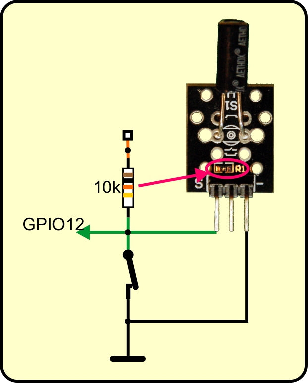
Image 5: Function of tilt switch KY-002
In the shown position of the module the switch is closed. GPIO12 is therefore at GND potential. This corresponds to a logical 0. In this state our counter is running. If we turn the tilt switch upside down, the contact is opened, which corresponds to a logical 1. Unfortunately we can't use the 10kOhm resistor on the PCB, because this would pull GPIO12 firmly against +3.3V already when booting the controller. The consequence of this would be that the controller cannot start. But on the other hand GPIO12 must be at +3.3V when the switch is open, because otherwise we can't reliably read in a 1.
The solution to this problem is simple. The ESPs have their own internal pullup resistor for each input, which can be switched on and off. And I switch it on for GPIO12 only when the boot process is already finished, namely in the program.
The program looks like this so far. All outputs are set to zero immediately after the declaration, the LEDs are all off.
from machine import Pin
contact=Pin(12,Pin.IN, Pin.PULL_UP)
one=Pin(13,Pin.OUT,value=0)
of two=Pin(5,Pin.OUT,value=0)
foursome=Pin(4,Pin.OUT,value=0)
six=Pin(14,Pin.OUT,value=0)
Next, I define a list. This is equivalent to a one-dimensional array in C. In MicroPython, a list can contain any elements without having to specify the type.
>>> from machine import Pin
>>> L=[1, 2.34, "one string", Pin(12)]
>>> L
[1, 2.34, 'one string, Pin(12)]
My list led contains the four pin objects for the LED control I just defined. This allows me to access them via the index, the place number, of the elements in a for loop. The indexing of lists in MicroPython starts with the place number 0. four contains the pin object Pin(4) and is located at position 2.
led=[one,two,foursome,sixes]
>>> led=[ones,two,foursome,sixes]
>>> led[2]
Pin(4)
So that I don't have to write the two lines of the for loop six times into the program, I define in advance a function with the name switch. As input serves the parameter statewhich I write in the round brackets after the name. The function definition is introduced by the reserved word def. The header is terminated by a colon.
All lines of the function body that follow after the header line are indented by two (with uPyCraft) or four characters (with Thonny). This indentation allows MicroPython to recognize when the definition of the function body has come to an end. The next line that follows in the surrounding program is indented again by 2 or 4 character positions. Indentation in MicroPython corresponds to the pair of curly braces in C.
def switch(state):
    for i in range(4):
        led[i].value(state[i])
From a programming point of view, a loop is a block of instructions that can be run several times. This increases flexibility and saves program memory space, which is not exactly abundant in microcontrollers.
The counting loop with for uses the variable i as a run index, which automatically starts with 0 on the first run and is incremented by 1 on each subsequent run. This is controlled by the reserved word range. The 4 limits the range excluding. That is, the last value that i takes is 3, so the loop is run exactly 4 times. The header of all command structures in MicroPython ends with a colon, so does the header of the for loop. After that, it is always indented.
What does this line do now?
led[i].value(state[i])
Well, led[i] picks the i-th pin object from the list led, led[0] is pin(13) to led[3] that is pin(14). With the method value() we can query the state of a pin object or as here with value(state[i]) to set it. Namely, the state is assigned to the so-called tuple state at the position i.
A tuple is a similar data structure to a list. While the values of elements in lists are modified (lists are mutable), after the declaration the elements of a tuple immutable (tuples are immutable). However, like lists, tuples can also hold elements of different types. And like a list, a tuple is a sequential, ordered data type. This means that the elements are always listed in the order in which they were declared. For better understanding, here are a few experimental lines that have nothing to do with our program. I will take up the further discussion of it right after this.
Example list:
>>> a=4
>>> L=[5.689,23,a,}, "test",a+16]
>>> L
[5.689, 23, 4, 'test', 20]    # Value of a is taken over not the reference (reference)
>>> a=9    # change has no influence on the values in the list
>>> L
[5.689, 23, 4, 'test', 20]
>>> L[3]
'test'
>>> L[2]=a    # List element 2 receives a new value
>>> L
[5.689, 23, 9, 'test', 20]
Example tuple:
>>> a=4
>>> t=(2.34,5,a,a+3) # value of a is taken over not the reference (reference)
>>> t
(2.34, 5, 4, 7)
>>> a=9 # change has no influence on the values in the list
>>> t
(2.34, 5, 4, 7)
>>> t[3]
7
>>> t[1]=12.7 # elements in the tuple cannot be changed
Traceback (most recent call last):
File "" , line 1, in <module>
TypeError: 'tuple' object does't support item assignment
Back to the program. The ring counter is still missing, which should finally control the outputs for the LEDs.
n=1
while True:

    if contact.value()==0:
        n= n+1 if n<6 else 1
        if n == 1:
            switch((1,0,0,0))
        if n == 2:
            switch((0,1,0,0))
        if n == 3:
            switch((1,1,0,0))
        if n == 4:
            switch((0,1,1,0))
        if n == 5:
            switch((1,1,1,0))
        if n == 6:
            switch((0,1,1,1))
In n I put the number of the dice, it starts with 1. Then it goes into the while loop.
After the reserved word or keyword while is followed by a conditional expression, which is used in the evaluation of the True (true) or False (false). True and False are truth values or also boolean values. The data type bool only these two values are available. The while loop is run through until the condition returns False. But this will never happen, because True is and remains True. We are dealing with an infinite loop here. Because the loop body contains the main part of the program, this loop is called Main loop or Main loop.
if (if) introduces a program structure that is used to execute a statement block once if the expression after the if keyword has the state True is returned. The expression here is a comparison. I read the state of the tilt switch and check if the value is 0. The comparison operator consists of two "=" characters. This is often overlooked and then leads to the reporting of a syntax error, whose cause and locality, especially at the beginning, is not immediately seen. Further comparison operators are <, <=, >, >= and !=. The last symbol stands for unequal. The if line is also terminated with a colon. I will get to the highest level of the if construct when I discuss the next but one program wuerfel3.py.
If the switch does not return the value 0 but a 1, then the value of the expression is False, and nothing happens, the next run starts immediately. If the switch was closed at the moment of the query, then we end up with the first statement of the if block, which is of course - quite rightly - indented.
n= n+1 if</=,> n<6 else 1
The line contains a conditional expression and is syntactic sugar (Peter J. Landin circa 1960), that is, we have here a notation that combines several lines of code into one line. In the long text it would look like this:
if n<6:
    n = n +1
else:
    n = 1
The else line also contains the colon, the following block is indented. Both notations are an extension of the simple if construct and are identical in their effect. The way of speaking exactly reflects the behavior.
Increase n by 1, if n is less than 6, otherwise set n to 1
>>> n=5
>>> n=n+1 if n<6 else 1
>>> n
6
>>> n=n+1 if n<6 else 1
>>> n
1
By the way, the colons are omitted in the conditional expression!
n has now a value between 1 and 6 including the interval limits. Depending on the value, the LEDs must be switched on or off. This is done by the function switch(), to which we give a tuple with the switching states of the pin objects as argument. The order corresponds exactly to that of the elements of the list led. Tuples are always written with round brackets. When functions are called, the arguments are also enclosed in round brackets. The result here is that the sequence of numbers for the switch states is enclosed in two pairs of round brackets, the inner pair for the tuple, the outer pair for the argument list. The quad tuples are used when calling switch() to the parameter state parameter. What the function does with it, I have already described above.
Have you plugged the circuit together and connected it to the PC? Then now enter the program text in an editor window of Thonny or load the file cube.py and open it in an editor window. Press F5 to start the program.
As long as you hold the tilt switch upright, all seven LEDs light up. The switching on and off at the different eye numbers is so fast that eye and brain cannot follow it. We perceive a slightly flickering, general glow. If we turn the switch upside down, the last counting state remains and the LEDs show the usual dot pattern of one side of the cube.
The randomness and chaotic behavior of the cube, which is what matters in dice rolling, is reflected in this first program only in the amount of time we hold the tilt switch upright. The counting process is anything but chaotic. I want to change this in a second approach.
Getting to grips with chance
The second program, just like the first, has 39 lines of code, comments and blank lines included. This is not by chance, because I just replaced one line by another, added an import line and removed the line with the default of n omitted.
From
n = n+1 if n<6 else 1
becomes
n = random.getrandbits(8) % 6 + 1
MicroPython provides a module for generating random numbers. In the import section I include this module in the program.
from machine import Pin
import random
The part up to the while loop we already know, the line with n = 1 I have, as already mentioned, stepped in. The while loop remains, except for this line:
n = random.getrandbits(8) % 6 + 1
As soon as and as long as the tilt switch is closed, now actually a randomly determined number with 8 bits, thus a byte, is diced. From this value I calculate the division remainder to the divisor 6. So for example 0b01101110 = 0x6E = 110 becomes the value 2. Because 110 : 6 = 18 remainder 2. 0b01101110 is the representation of the number 110 in the binary system, 0x6E is the equivalent in the hexadecimal system. The division remainders modulo 6 are in the range 0..5. But I need the range from 1 to 6, so without further ado a 1 is added. With this value for n we go on to the display.
For a new test start the program dice1.py in a new editor window.
From 1 make 2
If we have already dealt with the serial data types list and tuple, then let's use their advantages to shorten the program wuerfel1.py by 10 lines with the same performance. Here is the listing.
# wuerfel2.py
#
# pin translator for ESP8266 boards
# LUA pins D0 D1 D2 D3 D4 D5 D6 D7 D8
# ESP8266 pins 16 5 4 0 2 14 12 13 15
# SC SD
from machine import Pin
import random
contact=Pin(12,Pin.IN)
one=Pin(13,Pin.OUT,value=0)
of two=Pin(5,Pin.OUT,value=0)
foursome=Pin(4,Pin.OUT,value=0)
six=Pin(14,Pin.OUT,value=0)
#
led=[ones,two,foursome,sixes]
image=((1,0,0,0),(0,1,0,0),(1,1,0,0),(0,1,1,0),(1,1,1,0),(0,1,1,1))
def switch(state):
for i in range(4):
led[i].value(state[i])
while 1:
if contact.value()==0:
n=random.getrandbits(8) % 6
switch(image[n])
What could be more obvious than to collect the switching information for the LEDs in a tuple. The data type tuple is more resource efficient than the type list. Because I only need the ability of an ordered, serial access to the status elements, the use of a tuple is sufficient. For the same reason, for the indication of the switching states of the LED groups, I also used the type tuple used. By the way, again for the same reason, I would have used for led instead of the type list you can also use the type tuple but then I would have had no reason to introduce you to the list data type.
The cube at its best
Surely you've noticed some increase in requirements. What comes next digs even deeper into MicroPython's treasure chest.
Circuit-wise it will be simpler and visually nicer, program-wise it will be a bit more demanding, but don't worry, step by step we'll get it right. Let's start again with the schematics for ESP32 and ESP8266. For the matrix cube I chose an ESP8266 D1 mini V3 as controller. It is small, can be placed together with the other two modules well on a mini breadboard, but can also be installed in a small housing to save space.
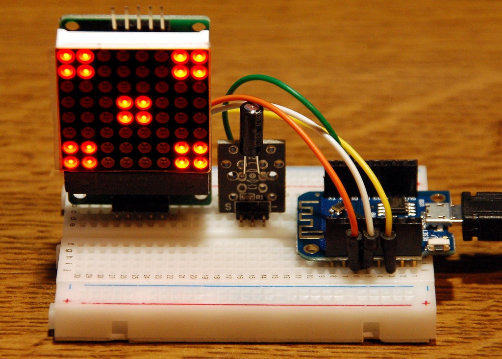
Image 6: Cube with matrix element and D1 mini

Image 7: Cube with matrix display and ESP32

Image 8: Cube with matrix display and ESP8266 D1 mini V3
A device with 64 LEDs in an 8 by 8 arrangement replaces the 7 LEDs. To control the 8 by 8 LED matrix we don't need 64 wires, but apart from the power supply with 5V and GND we only need three more, so 5 wires in total. This is due to the fact that a driver module MAX7219 is hidden under the actual display, which makes the LEDs light up according to our wishes. How this works exactly will be explained in a separate blog post titled "The Mammoth Matrix Display under MicroPython". covered. We communicate the wishes to the MAX7219 via the so-called SPI bus (Serial Peripheral Interface). The data is transferred via the said three lines MOSI, SCK and CS. CS tells the MAX7219 that data will arrive shortly, on the line MOSI (Master Out Slave IN) the data levels are present (0 or 1) and on the SCK line the ESP32 or ESP8266 tells the MAX7219 when the latter should read the data bit. The background is not important for this project, so I won't go into it in detail. The setup of the SPI bus I leave to the module spibus. It contains a function definePins() which ensures that the lines are initialized according to the circuit diagrams. The controller type is selected automatically.
We also need to import the MATRIX class from the matrix8x8 module so that the commands to control the display become available.
What is a module? Modules are in MicroPython what a library is in the Arduino IDE, that is, a collection of program and data structures that you can use in addition to your own instructions. There, as here, they are mostly functions that serve as a link between program and connected hardware, so-called drivers.
The modules we used in the previous programs were already firmly integrated in the firmware of MicroPython. This is different for matrix8x8 and spibus. These two are available as MicroPython program files. Best you load matrix8x8.py and spibus.py right away and move them to the working directory of Thonny. Then select both of them with the CTRL key pressed and open the context menu with a right-click.
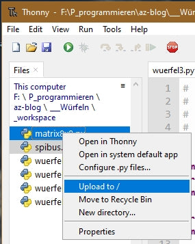
Image 9: Upload modules
Then send the files with a click on Upload to / to the flash of the controller. Now we come to the program.
import sys,os
from machine import Pin
import random
from matrix8x8 import MATRIX
import spibus
spi,cs=(spibus.definePins())
d=MATRIX(spi,cs,1)
contact=Pin(12,Pin.IN, Pin.PULL_UP)
After the imports I declare again the input contact for the line of the switch. The function definePins() from the module spibus defines the lines for the SPI bus depending on the controller type, sets up the necessary objects and then returns the SPI bus object, as well as the pin object for the CS line. The return object is a tuple, but I put it into the two variables spi and cs to unpack.
Then I create a matrix display object with this data d with an 8 by 8 element. These program lines can also be copied into REPL and
>>> import sys,os
from machine import Pin
import random
from matrix8x8 import MATRIX
import spibus
contact=Pin(4,Pin.IN)
spi,cs=(spibus.definePins())
d=MATRIX(spi,cs,1)
Hardware bus 1: Pins fixed
SCK Pin(14), MISO Pin(12), MOSI Pin(13), CSPin(16)
MATRIX constructor: 8 x 8 pixel
The created objects are now queryable.
>>> spi
HSPI(id=1, baud rate=4000000, polarity=0, phase=0)
>>> cs
Pin(16)
>>> d
<MATRIX object at 3fff0a70>
In the next section, I define in terms of tuples, using binary notation, eight bytes each that give the pattern of the corresponding cube face, 1 is light again, 0 is dark. After that I summarize the six pattern tuples in the tuple state so that I can retrieve the patterns by their index.
>>> six
(195, 195, 0, 195, 195, 0, 195, 195)
>>> state[5]
(195, 195, 0, 195, 195, 0, 195, 195)
The tuple six stands in state at the 5th position. You remember, counting in serial data structures like tuples, lists and strings starts at 0.
In my main loop, I need a timer that delays displaying the pattern while dice are being rolled. Such an object is provided by the function TimeOut(). It returns the address of another function (compare()), which I can query at any point whether the set time has already expired or not. The backgrounds are too complicated in a tutorial for beginners, so I leave them out. Who nevertheless would like to go deeper, I refer gladly to a PDF documentwhich explains the mode of operation. For the time being, it is only important that the TimeOut() returns the function compare() then with True if the difference between the current system time in milliseconds and the start time is greater than the number of milliseconds in delay.
The function switch() I can save myself. Instead of this I use a method from the module matrix8x8. More about this in a moment.
delay=1000
n=1
show=TimeOut(delay)
In delay I set the delay time for the display and with n=1 I create the variable for the cube eyes, so that I don't get an abort in the while loop due to an indexing error in the tuple state tuple. In show I put the address of the function that gives me TimeOut() and which is trimmed to return after the milliseconds in delay the value True value. You will see how this works in a moment.
while 1:
    if contact.value()==1:
        d.clear()
        n=random.getrandbits(8) % 6
        show=TimeOut(delay)
    elif show():
        d.shape(0,state[n])
        d.show()
    else :
        pass
The loop is again the heart of the program. We already know the query on the contact. But the geometry of the matrix element and the contact module made me invert the contact query from closed to open. The two modules can then be placed side by side in a small breadboard. When the contact is open, I turn off the display, or better, I clear the display. That makes the method clear() from the module matrix8x8. After that a number from 0 to 5 is rolled, we already know that. Every time or as long as dice is rolled, respectively shaken, I readjust the timer.
Now comes something new, the expansion stage of the if structure announced at the beginning. With elif I can check again in the else branch of if if there is another situation that has not been tested for before. Here it is the call of the function show(). As long as the 1000 ms have not elapsed since the last place of the expiration time, wherever that took place, returns show() returns a False back. If the time is up, we get a True.
Then the pattern to which index n in tuple state may be replaced by the method shape() from the matrix8x8 package. The following show() makes the corresponding LEDs light up.
An else: concludes the if construction. To prevent MicroPython from reporting a syntax error, I added the statement pass statement, which is just there for form's sake, but does not execute anything. Actually, I could have omitted the else: completely, but then I wouldn't have been able to show the whole beauty of an if structure.
Now very quickly, program dice3.py in an editor window, start it, "dice" and be amazed what the matrix display produces. I guess you are curious about what else the matrix8x8 module has to offer. Just open the file in an editor window. Look at the function definitions with the parameter lists, then you have a clue what you can call with which arguments. The full effect shows up unfortunately only with displays with several elements, for example scroll, shift, blink, text output ...
Have fun researching and trying out and of course rolling the dice.


2 comments
Jürgen
Hallo, Klaus,
prüfe doch bitte nach, ob die Kugel im Neigungssensor klappert, wenn du das Modul schüttelst. Ich vermute, dass es am Kontakt liegt. Der Durchlauf wird gestoppt, wenn der Sensor auf dem Kopf steht.
Du kannst auch einfach den GPIO12 = D6 am ESP8266 von Hand mit einem Jumperwire mal kurz auf GND legen, dann sollten alle 7 LEDs leuchten. Legst du dann den Eingang kurz auf 3,3V, dann müssen die LEDs eine gewürfelte Zahl anzeigen.
Ein anderes Problem beim ESP8266 ist, dass er beim Booten bereits versucht, sich mit einem WLAN-Router zu verbinden, um einen Kontakt über Web-REPL, die Funkkonsole, aufzubauen. Kriegt er keine Verbindung, macht der Controller immer wieder einen Neustart. Warum die Macher von Micropython das so programmiert haben weiß ich nicht, meistens stört dieses Verhalten. Du kannst nach dem Booten folgendes versuchen:
(Nach jedem Neu-Flashen der Firmware:)
>>> import webrepl_setup
> d # fuer disable
Dann RST; Neustart!
Ich hoffe die Tipps führen zum Erfolg.
Viel Erfolg!
Jürgen
Klaus
ich habe die Schaltung nachgebaut – und auch die Programme installiert bekommen (8266). Leider stoppt das Programm nicht bei Betätigung des Neigungssensors – der Code scheint dauerhaft durchzulaufen – die LEDs flackern … zeigen aber keinen Würfelwert an