Valentine's Day is just around the corner, a date on which we show our affection and love for special people in our lives. A gift that we always have in mind is red roses because they have a special meaning. But after a few days, they lose their freshness and their appearance is no longer as beautiful as in the first few days.
In this project, we will produce a rose that we present in a box. This box will open with your hand when touched or approaching. She has a screen on which we can issue a message. It is a very original gift, and the most important thing is that we can make it ourselves with just a few materials and with all the love that we want to show a special person.
We use tissue paper for the petals of the rose because it is transparent. For the goblet leaves, the leaves, and the goblet, we take a DIN A4 sheet made of normal, white paper and the tube of a spray bottle for the stem. We will use a three-colored LED diode for the lighting of the rose.
The project box measures 10 x 10 cm and the rose is 7 cm high, the remaining 3 cm is the housing for all circuits.
Although the rose in the project only shines red, we can make them shine in the favorite color of the person who we give the box or create a color sequence. We also use a ring with 12 three-colored LEDs to highlight the green color and illuminate the box.
To open and close the box, we use a servo motor and as a button two capacitive sensors, which we will produce with only two wires and aluminum foil ourselves.
Required materials
|
1 |
|
|
1 |
|
|
1 |
|
|
1 |
|
|
3 |
|
|
2 |
|
|
2 |
|
|
1 |
|
|
1 |
MB 102 Breadboard kit with power supply, Breadboard and cables |
|
1 |
|
|
1 |
White normal paper |
|
1 |
Plastic spray filler |
|
1 |
Aluminum paper |
|
1 |
The box can be made from different materials. I chose balsa wood or poplar plywood. Suitable housing can also be created with a 3D printer.
Required software
- Arduino IDE
- Adafruit Neopixel Library (about library management or here)
- Wire Library (integrated)
- Adafruit gfx_library (about library management or here)
- Adafruit SSD1306 Library (about library management or here)
- Capacitivesor Library (about library management or here)
- Servo library (integrated)
- sketch in O
- sketch in O
Design and assembly of the rose
I now show how I make the flower. The template for the parts of the flower must be adapted to the size of the rose that we want to create.

Teiling paper is very thin and difficult to handle. To make the petals, first make a surface made of normal paper (1), two petals are sufficient. Then we have to create three petals from tissue paper and stick them together, whereby we have to make sure that their base areas have the same extent (2). For the chalice, the five sepals (3) and the two leaves (4) you take normal paper, paint them with a green felt pen and cut out small triangles on the edges of the leaves - the parts of the rose are ready. First glue the five sepals together into a seafares (5) and leave a 5 mm hole for the three -colored LED in the middle. Carefully bend the petals inwards and glue them onto the sepals (6).
The hose of any spray bottle is used for the stem of the flower (7). We solder the three -colored LED of the flower to wires that we put inside the tube. When the LED sits on the stem, we put it through the lower hole of the rose and stick the goblet to the goblet leaves. To close the upper hole of the rose, we create a circle of tissue paper, stick a thin strip on it, stick it on the rose and we have made our flower with love.

On the mini-breakboard we will install the microcontroller, the resistors, capacitors and, in our case, the 5 V equal power supply. All of this is placed in the lower part of our box. Inside the box there are the servo engine, the LED ring, the two capacitive sensors and inside the rose the three-colored LED diode.
Manufacture and description of the capacitive sensor
First of all, I will now explain how the capacitive sensor that we will use to open and close the box works and how to make it.

A capacitor consists of two plates that are separated by a dielectric. For our sensor we only need a 100 k-OHM resistance, a 22-pf condenser, a piece of aluminum film and cable.
As we can see in the circuit, we have a resistance in parallel with a capacitor and the recipient the piece of aluminum foil. Under normal conditions, the capacitor is charged by the transmitter PIN up to the supply voltage, the recipient pin reads the voltage that is stored in the 22 PF capacitor and remains stable. Our sensor is the piece of aluminum, which acts as one of the panels of a capacitor, and we or our fingers, as the other plate. The dielectric is the space between us and the piece of aluminum. The closer we get, the lower the value of the dielectric, and we reach a distance where we begin to guide electricity.
To illustrate the above explanations, the following circuit should be set up (Download of the circuit diagram):

For this, the Capacitivesor library must now be installed and the sketch capacitive_sensor_check.ino Loading. If we approach one of the aluminum film folks, the corresponding LED should light up. In the lines
long green_reading = Green_Sensor.Capacitive sensor(30);
the number is in brackets for the sensitivity of the sensor, which results from the number of screens over a certain period of time. You can change the value to adapt the detection.
The Sccketch code is simple and every line is explained so that it is very easy to track and analyze.
Circuit and description of the functioning of the overall project
The following image shows the electronic structure of all components used (Download of the circuit diagram):

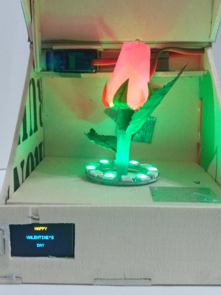
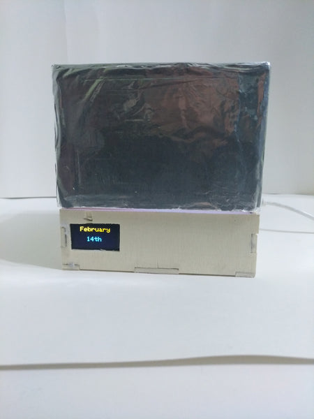
The operation is very simple: As soon as the sketch is started, the box is closed, there is no light inside and the OLED display shows the message "February 14". If you put the hand, finger or (depending on the sensitivity setting) the aluminum foil on the lid, the lid opens with the servo engine and the rose inside lights red (can also be set to any color), 6 of the 12 LEDs Green glow on the ring and reinforce the green of the flower and the message "Happy Valentine's Day" appears on the display. As long as we do not touch the piece of aluminum foil inside, the box does not begin to close, and when it closes, the LED stops glowing on the rose. The LEDs of the ring switch from green to white, so that the closed box remains illuminated inside. The display again shows the original message "February 14".
To open the box again, you have to touch the aluminum film of the box lid or approach it. When the box is open, the lid will not move if you touch the aluminum foil of the box because I wrote a condition in the sketch that I will show later.
Let's start with the analysis of the code of the sketch valentine_day_box.ino. First of all, the necessary libraries of the modules or components we want to use must be integrated. They contain the methods that we use, for example, to initialize a component or to carry out actions with these modules. The libraries that we illustrate are those of the OLED screen, I2C communication (wire), the capacitive sensor, the servomotor and the WS2812b RGB LED ring.
// 1.3 Inch OLED I2C 128x64 Pixel Display Libraries
#include <Wire.H>
#include <Adafruit_gfx.H>
#include <Adafruit_ssd1306.H>

// Library Required for Operation of the Capacitive Foil Sensor
#include <Capacitive sensor.H>

// servo motor library
#include <Servo.H>

// Led Ring WS2812B Library
#include <Adafruit_neopixel.H>
After we have integrated the libraries, we have to configure the properties of each module or component and implement an object for a component. The first component in which we carry out these measures is the LED ring. As you can see in the circuit, we have connected it to the digital PIN 10 in the first line of the following code. In the second line we indicate the number of LEDs contained in the ring, namely 12.
// Define Pin and Number of Leds on WS2812B Ring
#define Ring_Led 10
#define ring_led_count 12
In the following line we implement an object for the ring that we call ring. In the constructor of the object, we have to specify the number of LEDs (12), the PIN of the microcontroller (10) and the properties of the ring as parameters. These are the three -colored LEDs (RGB) with a working frequency of 800 kHz.
// ws2812b ring object
Adafruit_neopixel ring(ring_led_count, Ring_Led, Neo_grb + Neo_khz800);
In the following lines we configure a number of colors using RGB values for each LED, e.g. For example, for the color red, we have to activate the red LED and leave the green and blue LED deactivated. For the yellow color we switch on the red and green LED and let the blue LED switch off.
// WS2812B Ring Colors
uint32_t red = ring.Color(150,0,0);
uint32_t green = ring.Color(0,150,0);
uint32_t blue = ring.Color(0,0,150);
uint32_t yellow = ring.Color(150,150,0);
uint32_t purple = ring.Color(150,0,150);
uint32_t Light_blue = ring.Color(0,150,150);
uint32_t white = ring.Color(150,150,150);
The next component we configure is the OLED screen. Its features are 128 pixels wide and 64 pixels.
#define Screen_Width 128
#define Screen_height 64
In order to implement a display object, the constructor parameters that we have to take into account are the variables for the width and amount of the display, & wire is a call to an address in the I2C Communication Library Wire and -1 would be the connection of the reset-pin , if available.
Adafruit_ssd1306 display(Screen_Width, Screen_height, &Wire, -1);
The next two lines are the implementations of two objects of the capacitive sensor class for the detection of opening and closing the box. The first parameter is the transmitter pin, over which we supply the sensors with 5 VDC, and the second parameter is the recipient through which we can see the change of voltage.
Capacitive sensor touch_open = Capacitive sensor(4, 3);
Capacitive sensor touch_close = Capacitive sensor(6, 5);
For the configuration of the servomotor, we first implement the Servo_Box object of the class Servo and define a variable name to save the position value of the servo motor in degrees.
Servo servo_box;
intimately degree;
The last three lines of the definition block are the pins of the microcontroller, to which we connect the pins of the three -colored diode for the rose (7, 8 and 9) for the colors red, green and blue.
#define red_led 7
#define green_led 8
#define Blue_Led 9
The next block is the setup (), which is carried out only once and represents the initial configuration of the components in the power supply to the microcontroller and when starting. We start with the initialization of the serial IDE console, we also initiate the OLED screen and check whether it is connected via the address 0x3c via I2C Communication protocol. If it is not connected or the address is different, a message appears on the serial IDE console that informs us about it. Open the serial monitor (CTRG+ABRICK+M) for the output.
    Serial.Begin(9600);
    IF(!display.Begin(Ssd1306_switchcapvcc, 0x3c)) {            // Display Connection Check
          Serial.print(F("SSD1306 Allocation Failed"));
          for(;;);
    }
After initializing the screen, we want to display a message on it. To do this, we have to assign values to the parameters of the methods of the screen object. We set the color of the text and the font size (2 corresponds to a height of 16 pixels), position the cursor in column 20 and line 0, where we want to write "February" and set the cursor in column 40 and line to To write word "14". After we have assigned all the values of the text properties and the text ourselves, we provide the command () with Display.Display () to display the text described in the previous lines with the values for positioning, font size and color on the screen.
    delay(10);
    display.Clear display();                                     // Delete Screen Content
    display.SettextColor(White);                                // set color text
    display.SettextSize(2);                                     // set font size
    display.setcursor(20,0);                                    // Position The Cursor in Column 20 and Row 0
    display.print("February");                                  // Word to be displayed
    display.setcursor(40,30);                                   // position the cursor in Column 40 and Row 30
    display.print("14th");                                      // Word to be displayed
    display.display();                                          // Show all the above words with the settings
In the next line of the Setup ()-Blocks we state that we have connected the servo motor to PIN 12 of the microcontroller.
servo_box.Attach(12);
We also have to configure the output pins of the microcontroller, to which we connected the three-colored LED of the rose. Remember that we have defined three variables with the PIN numbers in the previous block.
    pin mode(red_led, OUTPUT);
    pin mode(green_led, OUTPUT);
    pin mode(Blue_Led, OUTPUT);
The last line of this block is the initialization of the LED ring.
ring.Begin();
Now we go to the loop ()-block that runs constantly as a permanent loop. It was simplified by methods to get a cleaner and more schematic code. In this block we only have the definitions of two variables for the values of the capacitive sensors to open and close the box. In addition, the simple conditional blocks to check the values and carry out the corresponding methods. Let us remember that the number in brackets ((30)) in the definition lines of the variables is sensitivity. It is the number of samples in a certain period of time that we can adapt to recognize the touch and carry out the corresponding action.
The detection takes place because, when we approach the aluminum foil, we create a "capacitor" between us and the box. Our approach means that the voltage value in the transmitter pin changes. The value is in the variables Open_Box or close_box saved. These variables are handed over to the IF conditions as arguments for checking. If a condition is met, the corresponding method is carried out.
    long Open_Box = touch_open.Capacitive sensor(30);        // variable to store the value of open box, sensitivity in parentheses

    long close_box = touch_close.Capacitive sensor(30);      // variable to store the value of close box, sensitivity in parentheses

    // Compare readings
    IF(Open_Box > 1) {
        Opening_box();              // Call to the Method of Opening the Box
    }

    IF(close_box > 1) {
        Closing_box();             // Call to the Method of Closing the Box
    }
We are now the method Opening_box analyze. If this method is carried out, the first command is reading the position of the servomotor. If the box is open, we don't have to carry out an action. If the position of the servo engine is higher than 175 degrees, it means that it is open. Then we leave the method and return to the Loop ()-Block.
    degree = servo_box.read();
    IF (degree>175) {                             // We check that if the servo engine position is higher than 170 degrees we exit and the lid does not mov.
      return;
    }
Otherwise, if the box is closed, we carry out the for loop and the position of the servo engine moves from the 90-degree position to 180 degrees. Then our rose immediately lights up red.
Else { for (intimately POS=90; POS<180; POS++) { // If it is Lower, The Box Open's at Slow Speed Up To 180 Degrees. servo_box.write(POS); delay(10); } }
color_led(255, 0, 0);
The WS2812B-RGB LED ring will make 6 of the 12 LEDs shine green. The commands we program for this run in the following order:
First we switch off all LEDs when you shine. We set the brightness to a value of 50 out of 255. Then we declare the LEDs we want to use and the color of each individual of them. Here we have to remember that they are listed from LED0 to LED11. Finally we conduct everything that was previously declared with the command ring.show () out of.
    ring.clear();                                 // Power off the LEDs
    ring.setbrightness(50);                       // set luminosity set to 50 out of 255
    ring.setpixelcolor(0, green);                 // We set the LED 1 of 12 of the Ring Lights Green
    ring.setpixelcolor(2, green);                 // LED 3
    ring.setpixelcolor(4, green);                 // LED 5
    ring.setpixelcolor(6, green);                 // LED 7
    ring.setpixelcolor(8, green);                 // LED 9
    ring.setpixelcolor(10, green);                // LED 11
    ring.show();                                  // turn on the leds with the configured color and Brightness.
When the box is open, we change the message on the screen in "Happy Valentine's Day"With the following code lines:
    display.Clear display();                       // Delete Screen Content
    display.SettextSize(1);                       // set font size
    display.setcursor(50,0);                      // position the cursor in column 50 and Row 0.
    display.print("Happy");                       // Word to be displayed
    display.setcursor(30,20);                     // Position The Cursor in Column 30 and Row 20.
    display.print("Valentine's");                 // Word to be displayed
    display.setcursor(55,40);                     // position the cursor in Column 55 and Row 40.
    display.print("Day");                         // Word to be displayed
    display.display();                            // Show all the above words with the settings
These lines are similar to those who previously in set up()-Block were described, where we also displayed the text "February 14" on the screen. With the analysis of the Opening_box ()-Method it will be easy for you to analyze the Closing_box ()-Blocks to carry out yourself because it is very similar.
The last method we have in the sketch is used to make the three -colored LED of the rose shine. This LED consists of three independent diodes, which shows the desired color through the visual mixture. It is 8-bit values from 0 to 255.
void color_led (intimately Value_red_Led, intimately Value_Green_Led, intimately Value_blue_Led) {

      // analog output method for the tricolor led (output pin, rgb value)
      Analogwrite(red_led, Value_red_Led);
      Analogwrite(green_led, Value_Green_Led);
      Analogwrite(Blue_Led, Value_blue_Led);
}
Sketch downloads:


Touch with little and high sensitivity:
We hope that you like this new project.


6 comments
Andreas Wolter
@A. Tommasi: könnten Sie bitte noch die Frage dazu fomulieren? Vielen Dank.
Grüße,
Andreas Wolter
AZ-Delivery Blog
A. Tommasi
Hallo Herr Wolter,
vielendanken für ihre Antwort dennoch habe ich eine frage, ich habe diesen kleinen Test geschrieben und der OLED 1.3" Funktioniert.
Ich bin kein Profi darum bitte ich Sie zu Helfen.
Ich danke Ihnen in voraus.
Grüße
Antonio Tommasi
#include
#include “SSD1306Ascii.h”
#include “SSD1306AsciiWire.h”
#define I2C_ADDRESS 0×3C
SSD1306AsciiWire oled;
void setup() {
Wire.begin();
Wire.setClock(400000L);
oled.begin(&Adafruit128x64, I2C_ADDRESS);
}
void loop()
{
oled.setFont(System5x7);
oled.clear();
oled.println(" Viel");
oled.print(" Erfolg!!!");
delay (2000);
}
Andreas Wolter
@A. Tommasi: auch da würde ich vermuten, dass es sich um einen anderen Chip handelt und daher die SD1306 Bibliothek nicht funktioniert. Es wird wahrscheinlich der SH1106 sein, wenn es sich um dieses Display handelt: https://www.az-delivery.de/products/1-3zoll-i2c-oled-display
Sie müssen dann eine andere Bibliothek verwenden und ggf. das Programm daran anpassen.
Grüße,
Andreas Wolter
AZ-Delivery Blog
A. Tommasi
Guten Tag,
ich habe das wunderbare Projekt nachgebaut und leider muss immer wieder feststellen das mit der OLED 1,3" nicht funktioniert mit der 0,96" ja warum?
ich würde über jede Hilfe dankbar sein.[ bitte um Hilfe ]
vielen danken in voraus.
MFG. A. Tommasi
Andreas Wolter
@Dieter: Möglicherweise haben Sie ein Display mit einem anderen Chip drauf. Die Displays ähneln sich stark. Das Problem hatte ich auch schon. Das ist aber nur eine Vermutung. Dann funktioniert die SSD1306 Bibliothek nicht.
Dieter
Danke für diese tolle Anwendung, die sich auch auf andere Gelegenheiten übertragen lässt. Mit dem Ansteuern des Dispaly habe ich ein problem: es gibt zwar keine Fehlermeldung, aber der Text wird nicht angezigt (es gibt ein random dot pattern auf dem Schirm). Das Display funktionier, wenn ich dieU8g2 library verwende…