Based on the successful blog posts about internet radio (Part 1, Part 2) I am introducing a clock radio today. The special thing is that an AZ-Touch with a 2.4 inch or 2.8 inch touchscreen is used. Operation takes place exclusively via the touchscreen. There are two alarm times, which can be assigned to any day of the week. Of course there is also a sleep timer. The brightness can be adjusted so that the display does not disturb you at night. With an optional LDR, the display brightness can be automatically adjusted to the room brightness. Volume, sleep time, display brightness and station selection can be adjusted via the touchscreen. Wake-up times and the stream URLs of the radio stations are configured via a web interface.
Required hardware
| Number | Component | annotation |
|---|---|---|
|
1 |
AZ touch with 2.4 inch display or 2.8 inch display |
|
|
1 |
|
|
|
2 |
|
|
|
1 |
|
|
|
1 |
|
|
|
1 |
|
|
|
1 |
Optional |
circuit
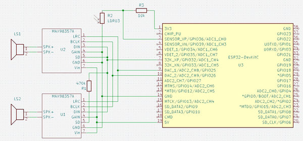
The circuit diagram only shows those parts that are not present in the AZ-Touch. The following images show how to expand the AZ-Touch circuit board accordingly. For the audio amplifiers, two 7-pin female connectors are attached to the perforated grid of the AZ-Touch to plug the audio amplifiers into. Also a 470 kΩ resistor. If you want to use the optional light sensor, you should solder a two-pin pin strip at 3.3 V and GND, as well as a single-pin pin at A0.
The second illustration shows how the wiring should be done on the back. The contours of the female connectors and the resistor are shown in yellow.

assembly
To accommodate the speakers, the AZ-Touch has a back wall that transforms it into a desk housing. The back panel can be made with a 3D printer. It also has an opening for the DC socket. File for printing the back panel.


There is one for installing the optional LDR mounting plate, onto which the LDR module can be screwed. A 5mm hole is drilled at the top of the housing and then the mounting plate is glued to the back wall with double-sided adhesive tape so that the LDR lies in the hole.
software
The sketch has been broken down into several parts for clarity. A function provided by the Arduino IDE is used for this purpose. If there are other “.ino” or “.h” files in the same folder in addition to the main sketch, which has the same name as the folder, the compiler will append them to the main sketch in alphabetical order.
Since the entire code has become very extensive, it is only available for download.
The ZIP file contains the folder with all associated files. It must be unpacked into the project files folder (often Documents\Arduino\). The individual parts are briefly described below. A detailed description can be found as comments in the code.
- radiowecker.ino: This is the main sketch. Global variables and data structures are defined.
- findNextAlarm() looks for the time and day of the week on which the alarm clock should be activated. The result is in the global variables alarmday for the day of the week and alarmtime saved for time in minutes. If no next appointment has been found, alarmday set to 8.
- set up() After initializing the serial port, the configuration data is read from the preferences. The setup functions of the individual program parts, with the exception of the web server and OTA, are then called. This is followed by establishing a connection to the local WLAN. If the connection was not successful, information about the configuration is shown on the display. If the connection is successful, the real-time clock is initialized. Now the setup for web server and OTA can also be called up.
- loop() first checks whether there are OTA requests and then whether there are requests for the web server. It checks whether the connection to the WLAN still exists. If the connection is established, the audio stream and the two encoders are checked for events. The time display is updated once a minute and a check is made to see whether the alarm clock needs to be activated. If the alarm time and day of the week match, the radio stream is started and played at the set volume. If the connection was interrupted for more than 5 minutes, the ESP32 will be restarted.
- 01_ziffern.ino: Defines 11 bitmaps with 50 x 70 pixels. These are the numbers 0 to 9 and the colon to represent the time.
- audio.ino: In this part, all functions related to the audio streams are implemented.
- setup_audio() prepares the system. Buffer and stream output are initialized.
- audio_loop() checks the status of the audio stream.
- MDCallback(void *cbData, const char *type, bool isUnicode, const char *string)
is called whenever new metadata is available in the received stream. Title type metadata appears on the display. - stopPlaying() stops playing the stream and releases the associated resources.
- bool startUrl(String url) Starts playing a stream from a given URL. If the start is not successful, false is returned.
- setGain() sets the volume to the value of the global variable
- fonts.h: Two fonts for the text display are defined here. One has a height of 9 pixels, the other 12 pixels. In addition to the 7-bit ASCII characters (codes 32 to 126), there are also the German umlauts Ä, Ö, Ü, ä, ö, ü, ß and the degree symbol (codes 127 to 134). There is a module for conversion tft_display.ino the function encodeUnicode(const char* src, char* dst), which converts text in UTF8 format so that it is displayed correctly on the display. For easier handling, two macros are defined: FNT9 for the 9-pixel font and FNT12 for the 12-pixel font.
- index.h: Contains the HTML pages for the web server. With the command sequence
const char MAIN_page[] PROGMEM = R"=====(
any text………
)=====";
Any text can be built directly into the program memory as a constant. This is very useful for HTML pages as they can then be designed and tested outside of the IDE. These pages use jQuery, Ajax and JavaScript. The advantage of Ajax for interactive pages is that when changes occur, only the changed part of the page is updated. Three HTML constants are defined.- OPTION_entry a template for entries in the selection list for the radio stations
- MAIN_page the main page with configuration and maintenance of the channel list
- CONFIG_page Page for entering the access data if the ESP32 is in access point mode for the initial configuration.
- knoepfe.h: HHere a bitmap with 320 x 64 pixels is defined that represents the heads on the configuration page. Each of the five buttons has a size of 64 x 64 pixels.
- ota.ino: The functions for updating the firmware via WLAN can be found here.
- setup_ota() the hostname and password are set. Callback functions are then registered.
- ota_onStart() is called when starting an OTA upload. The display is cleared and a corresponding message is shown in the first line
- ota_onEnd() is called after the upload has finished. A corresponding message is displayed.
- ota_onProgress(unsigned int progress, unsigned int total) is called up at regular intervals during the upload and provides information about the progress. The display shows the progress in percent and as a bar.
- ota_onError(ota_error_t error) is called when an error occurs. The error message is shown on the display.
- stations.ino: defines a program memory constant with the default channel list.
- setup_senderlist() fills the channel list in RAM with the channel list from the preferences. If there is no channel list there, the default channel list is used.
- restore(): Fills the channel list from the default channel list and saves it in the preferences. The function is helpful if the channel list is mixed up.
- saveList(): Save the station list from the RAM in the preferences.
- reorder(uint8_t oldpos, uint8_t newpos): Moves the sender entry at the position oldpos to the position newpos. Entries in between are moved accordingly.
- tft_display.ino: contains all functions for controlling the display and touchscreen.
- onTouchClick(TS_Point p): Callback function that is always called when you briefly tap the touchscreen. The parameter p indicates the point on the display that was tapped. The coordinates are x and p.y. The zero point is in the top left corner.
- setGainValue(uint16_t value): The volume slider is updated to the value passed.
- setBrightness(uint16_t value): The brightness slider is updated to the value passed.
- setSnoozeTime(uint16_t value): The sleep time slider is updated to the value passed.
- setBGLight(uint8_t prct): The brightness of the backlighting of the display is set to the transferred value in percent. If the value is 0, the brightness is set depending on the light sensor.
- selectStation(uint16_t x): Depending on the x position, the next or previous entry in the channel list is displayed on the configuration page. Entries that are not activated are skipped. If x < 50, the previous entry is displayed. If x > 270, the next entry is displayed. Nothing happens for all other values of x.
- toggleRadio(boolean off) : Depending on the value of the parameter off Playback of the MP3 stream is started or stopped. The display then switches to the clock display.
- toggleAlarm(): The alarm clock function is switched. From off to on and vice versa. The display then switches to the clock display.
- startSnooze(): The sleep time is started with the configured value. The display then switches to the clock display. If necessary, the radio will be turned on.
- changeStation(): With selectStation selected station is set as active station. The display then switches to the clock display.
- touch_loop(): Must be called from the main loop and is used to query the status of the touchscreen in order to detect touches.
- setup_display(): The display and touchscreen are initialized.
- textInBox(uint16_t x, uint16_t y, uint16_t w, uint16_t h, const char* text, uint8_t align = ALIGNLEFT, boolean big = false, uint16_t fc = ILI9341_WHITE , uint16_t bg = ILI9341_BLACK, uint8_t lines = 1 ): The passed text will be in a rectangle with the width w and the height H at the position x, y (top left corner). If the text is too long, it will be cut off at the last space between words. The alignment can be left, right or centered. Default is left. With the parameter big The font size can be selected with 12 pixels. Default is 9 pixels. Font color and background color can be chosen. Default is white on black. A multi-line display is possible. In this case, the line break always occurs at a space between words. Default is one line.
- updateTime(boolean redraw): The date and time display is updated. Is redraw true, the entire content will be reprinted, otherwise only the changes will be updated.
- displayDateTime(): Calls updateTime(false)
- showProgress(uint32_t prc): Displays a progress bar and the value in percent. Is called in connection with the software update.
- encodeUnicode(const char* src, char* dst): Walks in the text src the UTF8 characters ÄÖÜäöüß° so that they are shown correctly on the display. The result will be in dst The target string must exist in a sufficient size.
- showSlider(uint16_t y,float value, uint16_t vmax): A slider will be at the vertical position y The slider will change according to the value passed value positioned. The parameter vmax indicates the maximum value.
- showGain(): The volume setting bar in the configuration display is displayed.
- showBrightness(): The brightness setting bar in the configuration display is displayed.
- showSnoozeTime(): The bar for setting the sleep time in the configuration display is displayed.
- updateStation(): The name of the channel in the channel selection bar is updated.
- showStationList(): The channel selection bar in the configuration display is displayed.
- showCommand(): The configuration display is displayed at full brightness.
- showStation(): The name of the active station is displayed in the radio block.
- showTitle(): The metadata for the currently playing stream is displayed in the radio block.
- showRadio(): The radio block is displayed.
- showNextAlarm(): The date and time for the next alarm event are displayed on the bottom line.
- showDebugInfo(int16_t v1, int16_t v2, int16_t v3): This function is not used. However, it can be used to show the value of three integer numbers on the display in the bottom line.
- showClock(): The time is displayed. The display will be completely deleted beforehand. If the radio is switched on, the radio block is displayed. If the alarm clock function is active, the next alarm time is displayed.
- webserver.ino: Includes the setup and functions to respond to http requests.
- setup_webserver(): The individual functions for handling http requests are registered and the server is started on port 80.
- webserver_loop() It is checked whether there are new requests.
- handleRoot() is processing a request for the main page. If there is a connection to the local WLAN, the main page is sent to the client. If the ESP32 is in access point mode for the basic configuration, the configuration page is transferred. In this case, any existing parameters must also be processed in order to save the access data or trigger a restart.
- sendStations() responds to the Ajax command with the URL /cmd/stations. Sends the list of stations as an HTML option list. This list is then incorporated into the dropdown element in the client via Javascript.
- setAccessData() responds to the Ajax command with the URL /cmd/setaccess. The SSID, PKEY and NTP server configuration data are saved in the preferences.
- getAccessData() responds to the Ajax command with the URL /cmd/getaccess. The SSID, PKEY and NTP server configuration data are sent as a response. The end of the line is used as a separator.
- getAlarms() responds to the Ajax command with the URL /cmd/getalarms. The two alarm times and the respective alarm days are sent as a string. The end of the line is used as a separator.
- uint16_t stringToMinutes(String val): Converts a string in hh:mm format to the number of minutes.
- setAlarms() responds to the Ajax command with the URL /cmd/setalarms. The alarm times are expected as arguments al0 and al8 in the format hh:mm. The alarm days are expected in the arguments al1 to al7 and al9 to al15. They are converted into an 8-bit binary number.
- getStationData() responds to the Ajax command with the URL /cmd/getstation. The ID of the desired station is expected as an argument. The name, URL and enable flag of the specified station are sent as a response. The end of the line is used as a separator.
- setStationData() responds to the Ajax command with the URL /cmd/setstation. The ID of the desired station is expected as an argument. If the ID is valid, the data passed as an argument for the name, the URL and the enable flag are stored in the channel list.
- testStation() responds to the Ajax command with the URL /cmd/teststation. The URL to be tested is expected as an argument. Attempting to start playing the specified URL. If the attempt is not successful, the system switches back to the current station and responds with “ERROR”.
- endTest() responds to the Ajax command with the URL /cmd/endtest. The test ends by starting playback of the current station.
- restoreStations(): The station list is filled with the default stations and saved in the preferences.
- restart() responds to the Ajax command with the URL /cmd/restart. The ESP32 will restart.
- wlan.ino: Includes the ability to connect to local Wi-Fi or provide an access point when connection is not possible.
- boolean initWiFi(String ssid, String pkey) tries to connect to the local WLAN with the specified access data. If no SSID was specified or the connection attempt is unsuccessful, an access point is started. The configuration page can then be accessed via this access point from a browser at the address 192.168.4.1.
In order for the sketch to be compiled, the Arduino IDE must be prepared accordingly. By default, the Arduino IDE supports a large number of boards with different microcontrollers, but not the ESP32. In order to create and upload programs for these controllers, a support software package must be installed.
First you need to tell the Arduino IDE where to find the additional data it needs. To do this, open the menu file the point Presets. In the preferences window there is an input field called “Additional board administrator URLs”. If you click on the icon to the right of the input field, a window opens in which you can enter the URL https://raw.githubusercontent.com/espressif/arduino-esp32/gh-pages/package_esp32_index.json can enter.
Now select the board management in the Arduino IDE under Tool → Board.
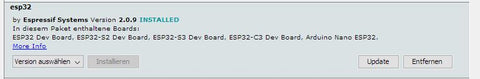
A window opens listing all available packages. To narrow down the list, enter “esp32” in the search field. Then you only get one entry in the list. Install the esp32 package. If the package was already installed, please check whether you have version 2.0.9.
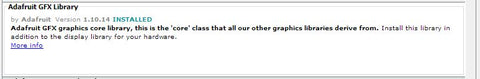
For the display you need two libraries that can be installed via the Arduino library management. This is the library “Adafruit_ILI9341” in version 1.5.10

and the library “Adafruit_GFX” in version 1.10.14.
Two additional libraries are required for the touchscreen. This is “XPT2046_Touchscreen” in version 1.4.0

and “Touchevent” in version 1.3.0

The core of this project is the library “ESP8266Audio” by Earle F. Philhower in version 1.9.7.

This library makes it possible to read, decode and play back various digital audio streams via different output channels. The program memory, the internal RAM, a file system, an SD card, an HTTP stream, or an ICY stream can be used as input. The ICY stream is typically used by Internet radios.
WAV, MOD, MIDI, FLAC, AAC and MP3 files can be decoded. MP3 is required for the web radio. Finally, the output can be in memory, files or I2S.
When all libraries are installed, the sketch can be compiled and uploaded to the hardware.
Danger! Since the sketch consists of numerous parts, it can take a long time to compile, especially the first time. For the ESP32 package and the ESP8266audio library, it is important to use the specified versions because the audio library was programmed very closely to the hardware.
If you want to save yourself the hassle of compiling, you can download the compiled firmware here and upload it directly to the ESP32.
To upload the binary file you need a utility program that can be downloaded free of charge from Espressif.Flash Download Tools
You need to download and unzip the ZIP file. Then you can start the included program flash_download_tool_3.9.5.exe. A window for selecting the controller appears.

Here you select ESP32 as the chip type and Develop as the work mode. The program continues with OK. The tool's working window appears.

Connect the ESP32 to the computer using a USB cable and select the serial port used at the bottom right. In the top line, set the path to the downloaded BIN file for the clock radio. 0x10000 must be entered as the destination address. Select all other settings as shown in the figure. Now you can click on “START”. The upload begins. When everything is finished, the green “IDLE” area changes to blue with the text “FINISH”. The ESP32 now has the firmware for the radio alarm clock and can be put into operation. The compiled BIN file only works with the current version of AZ-Touch.
Installation
When you first start up, there are no preferences yet. Therefore, a connection to the local WiFi cannot be established. An access point with the SSID “radioweckerconf” without a password is started. A corresponding message appears on the display.

A connection to this access point can now be established using, for example, a smartphone. The configuration page can then be accessed in a browser using the address 192.168.4.1.

After rebooting, you should be able to connect to the local WiFi successfully. The current time and date should be shown on the display.

If you tap anywhere on the display, the operating page appears.

There are three sliders for volume, brightness and sleep time. The settings are changed by tapping on the desired position. A special feature applies to the brightness. If set to 0, if the optional LDR is present, the brightness is adjusted to the ambient brightness.
In the fourth line you can see the current radio station. Using the two buttons on the left and right, stations can be selected from the station list.
At the bottom is a row of buttons.
 The radio turns on or off. The display returns to the time display. If the radio was switched on, the radio block with the station name and the metadata (e.g. name of the song currently being played) appears under the time display.
 The sleep time starts. If the radio is not turned on, it will turn on. The display returns to the time display. When the set sleep time has passed, the radio switches off automatically.
 The alarm clock function is switched on or off. The display returns to the time display. If the alarm clock has been switched on, the day of the week and the time when the alarm clock will next be triggered appear at the bottom of the display. If the displayed day of the week and time are correct, the radio will automatically turn on.
 The selected station is adopted as the active station. If the radio is currently switched on, the stream automatically switches to the new station. The display returns to the time display.
 The display returns to the time display.
If there is no activity for 10 seconds, the display automatically returns to the time display. All settings changes are saved in preferences. The operating page is always displayed at full brightness.
Configuration and editing of alarm times and the station list
The configuration page should be accessible via the URL http://radiowecker/.

In the upper part the access data and the NTP server can be changed. The changes will only take effect once the “Save” button has been clicked.
A restart can be triggered using the “Restart” button.
Next are the alarm times. Two alarm times can be set. For each of the alarm times, the days of the week on which the alarm times are to be applied can be selected.
The drop-down list below contains all channels in the channel list. Selectable channels have a black dot in front of the name. In the form below, the data for the selected station is displayed and can be changed. If the “Use” box is not checked, the station cannot be selected in the device. Since some URLs do not work, a new URL should be tested using the “Test” button. Clicking on this button starts playback of the URL on the device. Danger! The radio must be switched on on the device for testing. If playback does not work, it will immediately switch back to the current station and a message will be displayed. If playback is possible, a box with a button will appear. Clicking this button closes the box and ends the test. The current station is played again. The position of the selected station within the station list is displayed in the “Position” input field. By changing this value, the station can be moved to the specified position. Using the “Change” button, the changes for the selected station can be made permanent.
Firmware update via OTA
To update the program, it is not necessary to open the device and connect a USB connection. In the Arduino IDE you should see the following entry under the ports.

You can now upload a sketch via this port. For protection, the password “wakeup update” must be entered when prompted. Since the serial interface cannot be used, messages are shown on the display.

The article is available as a PDF here
Have fun replicating it.


201 comments
Bernhard FW
Schönes Projekt !! Danke dafür! einzig: das “rundum-Gehäuse” (zum Hinstellen und für die Lautsprecher) könnte mit dabei sein… – habe ich jetzt drucken lassen (€ 19,50)
Aber ich habe noch Probleme mit der SW… alle HW zusammengebaut…
Die Binarys geflasht (ging mit Windows 11 nicht…) – aber dann mit Ubuntu
2,8" Touchscreen/Display ohne Funktion (schwarz) – mit Arduino IDE Radiowecker.ino gibt es jede Menge Errors:
Hat einer eine Idee?
In file included from /home/bernhard/Arduino/libraries/ESP8266Audio/src/AudioFileSourceHTTPStream.cpp:23:
/home/bernhard/Arduino/libraries/ESP8266Audio/src/AudioFileSourceHTTPStream.h:56:5: error: ‘WiFiClient’ does not name a type
56 | WiFiClient client;
| ^~~~~~~~~~
/home/bernhard/Arduino/libraries/ESP8266Audio/src/AudioFileSourceHTTPStream.cpp: In member function ‘virtual bool AudioFileSourceHTTPStream::open(const char*)’:
/home/bernhard/Arduino/libraries/ESP8266Audio/src/AudioFileSourceHTTPStream.cpp:42:14: error: ‘client’ was not declared in this scope; did you mean ‘Client’?
42 | http.begin(client, url);
| ^~~~~~
| Client
/home/bernhard/Arduino/libraries/ESP8266Audio/src/AudioFileSourceHTTPStream.cpp: In member function ‘virtual uint32_t AudioFileSourceHTTPStream::readInternal(void*, uint32_t, bool)’:
/home/bernhard/Arduino/libraries/ESP8266Audio/src/AudioFileSourceHTTPStream.cpp:105:3: error: ‘WiFiClient’ was not declared in this scope
105 | WiFiClient stream = http.getStreamPtr();
| ^~~~~~~~~~
/home/bernhard/Arduino/libraries/ESP8266Audio/src/AudioFileSourceHTTPStream.cpp:105:15: error: ‘stream’ was not declared in this scope; did you mean ‘std::io_errc::stream’?
105 | WiFiClient *stream = http.getStreamPtr();
| ^~~~~~
| std::io_errc::stream
In file included from /home/bernhard/.arduino15/packages/esp32/tools/esp-x32/2302/xtensa-esp32-elf/include/c++/12.2.0/ios:42,
from /home/bernhard/.arduino15/packages/esp32/tools/esp-x32/2302/xtensa-esp32-elf/include/c++/12.2.0/ostream:38,
from /home/bernhard/.arduino15/packages/esp32/tools/esp-x32/2302/xtensa-esp32-elf/include/c++/12.2.0/bits/unique_ptr.h:41,
from /home/bernhard/.arduino15/packages/esp32/tools/esp-x32/2302/xtensa-esp32-elf/include/c++/12.2.0/memory:76,
from /home/bernhard/.arduino15/packages/esp32/hardware/esp32/3.0.1/libraries/HTTPClient/src/HTTPClient.h:34,
from /home/bernhard/Arduino/libraries/ESP8266Audio/src/AudioFileSourceHTTPStream.h:26:
/home/bernhard/.arduino15/packages/esp32/tools/esp-x32/2302/xtensa-esp32-elf/include/c++/12.2.0/bits/ios_base.h:204:24: note: ‘std::io_errc::stream’ declared here
204 | enum class io_errc { stream = 1 };
| ^~~~~~
In file included from /home/bernhard/Arduino/libraries/ESP8266Audio/src/AudioFileSourceICYStream.h:31,
from /home/bernhard/Arduino/libraries/ESP8266Audio/src/AudioFileSourceICYStream.cpp:28:
/home/bernhard/Arduino/libraries/ESP8266Audio/src/AudioFileSourceHTTPStream.h:56:5: error: ‘WiFiClient’ does not name a type
56 | WiFiClient client;
| ^~~~~~~~~~
/home/bernhard/Arduino/libraries/ESP8266Audio/src/AudioFileSourceICYStream.cpp: In member function ’virtual bool AudioFileSourceICYStream::open(const char)‘:
/home/bernhard/Arduino/libraries/ESP8266Audio/src/AudioFileSourceICYStream.cpp:49:14: error: ’client’ was not declared in this scope; did you mean ‘Client’?
49 | http.begin(client, url);
| ^~~~~~
| Client
/home/bernhard/Arduino/libraries/ESP8266Audio/src/AudioFileSourceICYStream.cpp: In member function ‘virtual uint32_t AudioFileSourceICYStream::readInternal(void*, uint32_t, bool)’:
/home/bernhard/Arduino/libraries/ESP8266Audio/src/AudioFileSourceICYStream.cpp:118:3: error: ‘WiFiClient’ was not declared in this scope
118 | WiFiClient stream = http.getStreamPtr();
| ^~~~~~~~~~
/home/bernhard/Arduino/libraries/ESP8266Audio/src/AudioFileSourceICYStream.cpp:118:15: error: ‘stream’ was not declared in this scope; did you mean ‘std::io_errc::stream’?
118 | WiFiClient *stream = http.getStreamPtr();
| ^~~~~~
| std::io_errc::stream
In file included from /home/bernhard/.arduino15/packages/esp32/tools/esp-x32/2302/xtensa-esp32-elf/include/c++/12.2.0/ios:42,
from /home/bernhard/.arduino15/packages/esp32/tools/esp-x32/2302/xtensa-esp32-elf/include/c++/12.2.0/ostream:38,
from /home/bernhard/.arduino15/packages/esp32/tools/esp-x32/2302/xtensa-esp32-elf/include/c++/12.2.0/bits/unique_ptr.h:41,
from /home/bernhard/.arduino15/packages/esp32/tools/esp-x32/2302/xtensa-esp32-elf/include/c++/12.2.0/memory:76,
from /home/bernhard/.arduino15/packages/esp32/hardware/esp32/3.0.1/libraries/HTTPClient/src/HTTPClient.h:34,
from /home/bernhard/Arduino/libraries/ESP8266Audio/src/AudioFileSourceICYStream.h:26:
/home/bernhard/.arduino15/packages/esp32/tools/esp-x32/2302/xtensa-esp32-elf/include/c++/12.2.0/bits/ios_base.h:204:24: note: ‘std::io_errc::stream’ declared here
204 | enum class io_errc { stream = 1 };
| ^~~~~~
In file included from /home/bernhard/Arduino/libraries/ESP8266Audio/src/AudioGeneratorMIDI.cpp:69:
/home/bernhard/Arduino/libraries/ESP8266Audio/src/libtinysoundfont/tsf.h: In function ’void tsf_channel_midi_control(tsf, int, int, int)’:
/home/bernhard/Arduino/libraries/ESP8266Audio/src/libtinysoundfont/tsf.h:2100:1: error: insn does not satisfy its constraints:
2100 | }
| ^
(insn 883 353 354 51 (set (reg:SF 19 f0 371)
(mem/u/c:SF (symbol_ref/u:SI (“*.LC223”) [flags 0×2]) [0 S4 A32])) /home/bernhard/Arduino/libraries/ESP8266Audio/src/libtinysoundfont/tsf.h 49 {movsf_internal}
(nil))
during RTL pass: postreload
/home/bernhard/Arduino/libraries/ESP8266Audio/src/libtinysoundfont/tsf.h:2100:1: internal compiler error: in extract_constrain_insn, at recog.cc:2692
0×706575c29d8f __libc_start_call_main
../sysdeps/nptl/libc_start_call_main.h:58
0×706575c29e3f __libc_start_main_impl
../csu/libc-start.c:392
Please submit a full bug report, with preprocessed source (by using freport-bug).
Please include the complete backtrace with any bug report.
See <https://gcc.gnu.org/bugs/> for instructions.
Multiple libraries were found for “SD.h”
Used: /home/bernhard/.arduino15/packages/esp32/hardware/esp32/3.0.1/libraries/SD
Not used: /home/bernhard/.arduino15/libraries/SD
exit status 1
Compilation error: exit status 1
-——
Nachdem ich die kompilierte Firmware (Binaries) geflasht hatte tat sich nichts… Touchscreen schwarz…
Dann habe ich den Flashspeicher gelöscht und mittels Arduino IDE mit Board "ESP32 DEV Module und Port ttyUSB0 das sketch Radiowecker.ino versucht hochzuladen und dabei gab es obige Errors…
Hat einer eine Idee, was da falsch käuft bzw. wie man ein Debugging machen kann ?
Danke Euch !!
Lionel
Hello
I’ve requested to a supplier (Abeille 3D) to print the back panel for me.
But the just told me that they found a gap between the main body and the rims (the part that insert into the front panel).
I tried to look at the STL file, but it’s a merged one and almost impossible to modify the design.
Is the non merged STL file available?
Did someone experience the same issue?
Any good idea is welcome :)
Thanks in advance
Lionel
Lionel
Hello
I’ve downloaded the STL for the rear-box.
As I don’t have a 3D printer, I requested an online service for it (abeille 3D)
But they told me that the design have a gap between the main body and the rim (the one that is inserted in the front-box)
I looked at the file, but it’s a merge design and not possible to see anything.
Did someone have another STL file?
Any idea is welcome :)
Thanks for the great job done on that project.
MFG
Lionel
kunigunde
Fehler Kompilieren ab Board Verwalter esp32 Version 3.0.0
Lösung hier:
https://github.com/beabel/radiowecker/discussions/50
Peter Kruger
@Karl J. Ziller
Ich hatte das gleiche Problem und musste https auf http ändern
Willi Wegemann
Hallo die Anfrage vom 1.5.24 hat sich auch erlrdigt.
Dieter Borgelt hat die Antwort im Beitrag vom 17.4.2024 gegeben.
Rotation von 3 nach 1 ändern
Danke
Willi
Udo
Vielen Dank für die prima Idee und Umsetzung. Der Aufbau hat soweit gut funktioniert. Was mir jetzt noch zum ultimativen Wecker fehlt ist ein Sonnenaufgang. Also ein licht was 10min vor dem Weckton langsam heller wird, wie der Sonnenaufgang. Das wäre eine Idee für den Wecker in Version3.0. Danke und weiter so.
Willi Wegemann
Hallo,
Meine Frage vom 29.04.2024 hat sich erledigt.Nach xmal lesen und probieren habe ich das System verstanden.
Nun stellt sich ein anderes Problem :
Die Kalibrierung de 2,4" Display stimmt nicht, das Diplay reagiert aber die Tippunkte liegen total daneben oder werden icht erreicht . Sonst bis jetzt zufrieden.
Gruss Willi
Willi Wegemann
Hallo,
habe den Internet Radiowecker mit Touch aufgebaut. Hat auf anhieb die Augen aufgemacht . Danach liegt der Fehler wohl bei mir , ich verstehe nicht wie ich ans WLAN komme. Das Display zeigt mir alles an ( SSID und IP ) .
Mein Problem : wie , wo gebe ich das ein ? Smartphon ,FritzBox oder PC .
Ich habe einfach keinen Plan und bitte um Hilfe für Unbedarfte.
Wenn ich aufs Display tippe kommt auch die Bedienseite ,das Radio klappt also, bis auf mein Unverständnis.
Danke im Voraus
Willi
Volker Niedenzu
Bei meinem gekauften Bausatz sind die Pins des mitgelieferten ESP32 mit ca. 6mm zu kurz, um eine sichere Kontaktüberdeckung in den Buchsenleisten zu haben. Ich muss die Buchsenleisten auf die andere Seite der Leiterplatte löten. Abgesehen davon, dass der ESP in der Längsachse krumm wie eine Banane ist und damit das Raster nicht mehr einhält. Den muss ich zum Einstecken dann “aufbiegen”. Durch die “Banane” steckt er zwar straff in den Löchern hat aber keinen sicheren Kontakt.
Karl J. Ziller
Schöner Radiowecker. Leider schaffe ich es nicht andere Sender einzustellen.
z.B.
HPR1: Traditional Classic Country
https://us2.maindigitalstream.com/ssl/7713
Dieter Borgelt
Es läuft auch auf einen AZTouch esp (alte Version) mit zwei Änderungen im tft_display:
tft.setRotation(3) TFT und Touch sind sonst 180 versetzt
#define TOUCH_IRQ 2 geänderte PIN-Nutzung alt IRQ2 neu IRQ27
kunigunde
V3.0.0 ist auf GitHub.
Ab sofort mit Alarm Einstellungen auf dem Touchscreen möglich.
Andreas K.
Zum Glück werden die Beiträge hier nicht zeitnah erneuert :-)
Dadurch hat sich meine Frage erledigt, ich habe es durch Forscherdrang selbst gelöst. Jetzt wird mit die Adresse angezeigt und ich muss nicht mehr die Fritzbox fragen, was z.B. im Urlaub mit einem fremden Netz eh nicht möglich wäre.
kunigunde
@Andreas K.
Dein Wunsch mit der IP auf dem Screen ist in Version 2.1.3 mit integriert.
@René Herzmann
Deine Version “antiflickering” ist seit Version 2.1.2 integriert. (Danke)
Github URL:
https://github.com/beabel/radiowecker
Online Flasher von Version 2.1.3:
https://ne-xt.de/esp_flasher/
Andreas K.
@Joachim Hofmann:
Der Sitz des Widerstandes ist uninteressant passt sowohl auf Reihe 4 oder 5. Die Lötpins sind alle unverbunden, nur ein Raster!
Der Wiederstand R3, übrigens 10kOhm, ist auf dem LDR-Modul schon verbaut, nimmst du eigenes Bauteile, dann musst du den natürlich einlöten.
@Jimbo
You need a Power Supply with 9-35V, DC.
Andreas K.
Hallo Radiobastler!
Ich habe nun endlich auch das Radio zusammengeklöppelt, nachdem ich schon die erste Variante mit dem 2-zeiligenbDisplay gebaut hatte. Ich habe die Software von Kunigunde genommen und bin sehr zufrieden. Eine Bitte hätte ich aber noch, kann man irgendwie die Anzeige der aktuellen IP-Adresse realisieren? Das wäre bequemer, wenn man das Radio über den PC oder das Smartphone bedienen will. ( Das geht übrigens absolut einfach und super, danke für das Feature!)
Jimbo
I have just received this internet radio kit.
Please can you tell me what DC power supply it needs – 5V or 3.3V?
Also, where can I buy a suitable power supply?
Joachim Hofmann
Ich bin gerade dabei den Radio zusammen zu bauen. Dabei sind mir zwei Sachen in der Dokumentation aufgefallen:
Auf Seite 2 im PDF ist die Vorder- und Rückseite der Platine abgebildet. Im ersten Bild ist der Widerstand in der 4. Spalte der Platine abgebildet, im zweiten Bild in der 5. Spalte.
Im Schaltplan gibt es noch einen R3 mit 20kOhm. In den beiden Bildern ist er nicht eingezeichnet und wird auch im Text nicht erwähnt. Entsprechend dem E-Book zum LDR wird kein Widerstand benötigt.
Gegebenenfalls sollte die Dokumentation entsprechend korrigiert werden.
Dylan Harris
I’ve bought this kit from AZ Delivery but they are unable to lend assistance. I have done the wiring for the amplifiers and all elements are assembled and processor now runs and runs sketch. However, when try to use the radio side of things it crashes and reboots. Have you any suggestions as to how I can diagnose this and have you any other wiring and assembly instructions as I could do with more information to check all components and wiring is correct. I have used the funny claw type connections for the processor but at a loss as to what the other two are used for. Hope you can help please?
YSC
Hallo Technik-Enthusiasten,
ich habe Fragen zum Touch-Radio: Welches Netzteil benötige ich dafür? Welche Spannung und Stromstärke sind erforderlich, um es problemlos zu betreiben? Es wird ein DC-Stecker mit einer 5,5 mm x 2,1 mm DC-Buchse verwendet. (Laut Beschreibung im Set)
Zweitens, gibt es eine Möglichkeit, das Touch-Radio mit einem DC-Stecker auf USB zu betreiben, indem ich es mit einem USB-Adapter verbinde?
Ich freue mich auf Ihre professionelle Antwort.
Vielen Dank voraus .
Reinhard Gränz
Bitte um Vergebung, die SSID war falsch, erläuft
Reinhard Gränz
Ergänzung zu Radiowecker findet keine Netzwerkdaten: Nach dem Neustart zeigt er die SSID an findet aber keine ip-Adresse und fällt wieder zurück auf 192.168.4.1
Reinhard Gränz
Hallo, ich habe meinen 10 Jahre alten O2-Router durch eine Fritzbox 7530 AX getauscht. Mit der Methode radioweckerconf 192.168.4.1 kann ich die SSID und das neue WLAN-Passwort eingeben. Beim Neustart findet er aber das WLAN nicht, obwohl er fast neben dem Router liegt. Er schaltet dann wieder in den o.g. Modus. Kann ich die Netzwerkdaten manuell eingeben oder welche Lösung gibt es noch.
René Herzmann
Hallo, dieses Projekt ist echt super. Konnte mir jetzt auch das Gehäuse drucken. Habe den Vollausbau durchgeführt. Nutze die Software von „kunigundes GitHub“. Bis jetzt hatte ich die Helligkeit nur per Slider eingestellt. Jetzt habe ich auch den LDR dazu genommen und diesen ins Gehäuse mit integriert. Bei Nutzung des LDR (Slider Helligkeit auf „0“) fing das Display an zu flackerte, das war nicht schön. Aus meinen anderen Projekten mit Display kannte ich das Problem schon. Habe folgende Änderung vorgenommen und nun schaut das „void setBGLight(uint8_t prct)“ jetzt bei mir so aus:
//adjust the brightness of the background led
void setBGLight(uint8_t prct) {
uint16_t ledb;
//if brightness is 0, we read the ambient light from LDR
if (prct == 0) {
static unsigned long prevMillis = -20000;
if (millis() – prevMillis < 10000) return;
prevMillis = millis();
ledb = analogRead(LDR) * 255 / 4096;
} else {
ledb = 255 * prct / 100;
}
if (ledb > 255) ledb = 255;
if (ledb < 3) ledb = 3; //minimal brightness
if (LED_ON == 0) ledb = 255 – ledb;
Serial.printf(“percent = %i LED = %i\n”, prct, ledb);
//set the LED
analogWrite(TFT_LED, ledb);
}
Jetzt wird nur alle 10 Sekunden die Helligkeit des Displays eingestellt. Den Wert kann man je nach Belieben ändern.
Peter Kruger
Mir ist noch nicht ganz klar, wie ich einen Kanal auswählen soll. Sowohl bei normaler Radionutzung als auch bei der Weckerfunktion. Wenn ich einen Kanal aus der Dropdown-Liste auf dem az-touch auswähle (also nicht über die Website), springt der Kanal regelmäßig entweder zum Standardkanal oder es passiert nichts (möglicherweise wird die Stream-URL nicht gefunden?). Was genau ist hier das Ministerium, das befolgt werden muss?
Gerald Lechner
@Martin Krüger: In diesem Zustand hat der Radiowecker eine AccesPoint mit der SSID radioweckerconf ohne Passwort gestartet. Sie müssen mit diesewm Netzwerk eine Verbindung herstellen, dann können Sie über die angezeigte IP-Adresse die Konfiguration vornehmen.
@Knut: Der Helligkeitswert wird in dauerhaft in der Konfiguration gespeichert. Das heißt Sie müssen ihn nur einmal auf 0 Stellen. Imp Programmcode radiowecker.ino können Sie in den Zeilen 122 und 123 folgende Änderung vornehmen:
122 bright = 0; //default value
123 //if (pref.isKey(“bright”)) bright = pref.getUShort(“bright”);
Damit ist der Wert nach dem Einschalten immer auf 0 auch wenn Sie vorher etwas anderes eingestellt haben.
Peter Kruger
@Martin Krüger
Did you change the wifi connection on your computer to connect to the SSID radioweckerconf network?
Knut
Hallo,
ich möchte gern in dem Prgrammcode die Helligkeit auf Null stellen. So dass der Lichtsensor auf hell- und dunkel regiert, ohne das ich dies erst, manuell einstellen muss.
Gibt es dazu eine Möglkichkeit?
Mit freundlichen Grüssen Knut
Martin Krüger
Hallo, ich habe die Hardware aufgebaut, bleibe jedoch an der Stelle stehen, wo die Abforderung kommt “connect to SSID radioweckerconf configuration on IP:192.168.4.1”.
Ich bekomme da keine Verbindung.
wie ist da der Werdegang?
brezel64
@Klaus-Peter Schildt: danke fürs antworten, da es hier doch manchmal recht lang dauert bevor die Kommentare veröffentlicht werden und weil kunigunde schon sehr gute Arbeit geleistet hat bin ich auf seinem Github Kanal fündig geworden.
Glaube gute Ideen sind dort genau an der richtigen Stelle.
brezel64
@Klaus-Peter Schildt: danke werde es testen, nutze jetzt die Version 2.1.1 von kunigunde der gute Arbeit geleistet hat.
Da hier die Kommentare manchmal lange brauchen bis sie veröffentlicht werden hab ich zu kunigundes GitHub Kanal gewechselt.
Sicherlich ist da jeder willkommen der sich einbringen will.
Klaus-Peter Schildt
@brezel64:Sorry seconds muss in der Basis Version natürlich global vereinbart sein!
Ich habe einiges verändert. Deswegen passte es bei mir.
Ein kleiner Tipp zum Test:
1. Die Zeilen am Ende von setup() ab diesem Kommentar ersetzen.
//remember the tick count for the timed event
tick=millis();//Wichtig, aktuelle Systemzeit holen
uint8_t Sekunden=ti.tm_sec;
uint8_t Minuten =ti.tm_min;
uint8_t Stunden =ti.tm_hour;
Serial.printf(“Startzeit Programm: %i:%i.%i\n”,Stunden,Minuten,Sekunden);
tick=(tick-Sekunden*1000);//Wichtig, 1. Startzeit von getLocalTime im loop setzen
start_conf=0;
2. Radio Controll Uhr mit Sekundenanzeige o.ä. als Referenz nutzen.
Bei Uhrzeit xx:xx.30 als Beispiel, den ESP32 RESET Button drücken.
Im seriellen Monitor sollten dann, nach der CPU Start Sequenz, die Stunden, Minuten und Sekunden vom Programmstart angezeigt werden. Mit einer Differenz von Referenz Start Zeit plus ca. 5-10 Sekunden Zeit für die Startsequenz CPU etc.
Die nächsten Zeit Aufrufe von getLocalTime im loop, müssten nun synchron zur Referenz erfolgen. Übrigens… Stunde und Minute werden auch zur Kontrolle, jede Minute, im Monitor angezeigt;-)
Show Time
Zeit = XX:XX
mfG. Peter
kunigunde
Version 2.1.1 ist veröffentlicht.
Ab jetzt auch mit Senderwechsel auf der Website.
Somit ist eine Benutzung komplett ohne Display möglich.
https://github.com/beabel/radiowecker/releases/tag/v2.1.1
Peter Kruger
@Klaus-Peter Schildt u.a.
In weckerradio.ino also the variable uint16_t seconds should be defined in the global section to avoid an error that secondes is unknown
Peter Kruger
Nach einer Reihe von Updates melden die Arduino IDE und der Radiowecker regelmäßig einen Authentifizierungsfehler. Wenn ich die Skizze über USB hochlade, ist das Problem für eine Weile behoben. Allerdings muss ich dafür immer den ESP32 vom Az-Touch entfernen, da das USB-Kabel nicht neben die angelöteten Pins und Elko passt (leider ist die Position von Elko vielleicht nicht ganz günstig gewählt, aber sie ist da) .
Gibt es dafür eine andere Lösung, damit ich über die Netzwerkbuchse wieder darauf zugreifen kann, ohne den ESP32-Sketch immer über USB laden zu müssen?
Gilles Pasquier
Hello, I finished assembling the kit. Now it works. I have 2 questions.
1) Where can I change the color of the time in the code ?
2) I added some french channels. The sounds is bad for these channels (kind of echo and vibration). When I listen them on a web browser it’s fine. Maybe the stream is not the same as german channels. What can I do ?
Thanks in advance.
Gilles Pasquier
@Gerald Lechner. I found the problem. I sed used the precompiled binary provided on the blog which seems to have a defect. I tried comiling myself the code, now it works.
brezel64
@Klaus-Peter Schildt: danke, habe es so umgesetzt : uint16_t seconds; in globale Variablen eingetragen, dann uint16_t seconds = ti.tm_sec * 1000; eingefügt und am setup() Ende tick=(tick-seconds); Uhrzeit ist aber immer noch ca 30sek nachhängend.
Spannende Sachen die du noch einbauen willst, leider sind meine C-Kenntnisse nicht gut genug um allein so etwas umzusetzen, in meiner Jugend hatten die Radios noch Röhren;-)
Aber macht mir Spass immer noch etwas dazu zu lernen.
kunigunde
@Dennis
Nein mit dem 0.6 verringerst du alle Werte die übergeben werden.
Normal wird zwischen 3 und 255 übergeben, danach zwischen 3*0.6 und 255*0.6 = zwischen 1.8 und 153. Somit alles verringert.
Gerald Lechner
@Gilles Pasquier: May be your ESP32 has not good contacts on the right side where the controller is located. Press it into the socket. Sometimes I had also this problem. The red led on the modul is on in this case.
Gilles Pasquier
Hello, I finished assembling the component except amplifiers. When I plug the 9V power adapter, the screen stays black. I made sure with a voltmeter that it is powered correctly.
The led on the EPS32 is on. What can I check else ?
Dennis
@kunigunde
Du hattest geschrieben:
@Dennis
Du könntest in der Function setBGLight vor analogWrite(TFT_LED, ledb);
diese Zeile einfügen:
ledb = ledb * 0.6;
damit verringerst du auf max 60%
Damit begrenze ich aber nur die maximale Helligkeit, oder?
Mir (eigentlich Familienangehöriger) ist ja die minimale Helligkeit ein kleines bisschen zu hell.
//adjust the brightness of the background led
void setBGLight(uint8_t prct) {
uint16_t ledb;
//if brightness is 0, we read the ambient light from LDR
if (prct == 0) {
ledb = analogRead(LDR) * 255 /4096;
} else {
ledb = 255*prct/100;
}
if (ledb > 255) ledb = 255;
if (ledb <3) ledb = 3; //minimal brightness, bei 0 geht es ganz aus
Wenn ich hier anstatt der 3 eine 0 einfüge, dann geht das Display ganz aus wenn es im Raum dunkel genug ist. Könnte man hier eine Variable einfügen welche in der Webkonfigurationsseite definiert werden kann. z.B. eine Checkbox, Haken drin ist 0 ansonsten 3.
Wenn das Display in der Nacht dann aus ist sollte es per tippen auf das Display für z.B. 5 Sekunden wieder heller werden um dann wieder auszugehen.
Wäre das ein umsetzbares Szenario?
Klaus-Peter Schildt
@brezel64: Zeilennummern sind andere, weil neuer Code eingefügt wurde. Einfach nach den originalen Kommentaren suchen.
//fill timestarukture ti, minutes and weekday with now => original Kommentar.
getLocalTime(&ti); //lokale Zeit holen.
Anschließend neu einfügen:
uint16_t second = ti.tm_sec * 1000; //Zeit Fenster präparieren für ersten tick Aufruf.
Dann weiter bis:
//remember the tick count for the timed event => original Kommentar.
tick=millis(); //aktuelle Systemzeit abfragen.
Anschließend Differenz bis 1. Time Event neu einfügen: Wird im loop() ausgewertet.
tick=(tick-seconds);
Fertig:-)))
Habe momentan alternativ die Touch Events durch TV Remote erweitert, der dicken Finger wegen;-)). Außerdem, sie durch Buzzer Click hörbar gemacht.
Im Kontext, das Einstellen der Weck Zeit etc. ohne Smartphon ermöglicht.
Mikrowellenradar Bewegungssensor wird zum löschen des Weckevent genutzt.
Bin dabei, auch Musik oder Sprache von SD Card zu verwenden. Beim wecken z.B.
Angedacht: Wetter und Raumklima Daten anzeigen.
Peter
Heinz Wanger
Ich bekomme keine Verbindung zur Fritzbox laut den eingegebenen Werten SSID und Passwort. Leider kann ich keine neuen Werte eingeben, da nach Restart, Verbindung zu radioweckerconf und Starten von Chrome Browser sofort ein Reset ausgelöst und mit den (eventuell) fehlerhaften Werten ein neuer Connect versucht wird. Ich habe die letzte Korrektur laut Nachtrag (Zeile 232 bis 238 …) angebracht und alles neu geladen. Leider kein Erfolg. Man muss wohl das EEPROM löschen um wieder auf den Anfang zu kommen, oder?
brezel64
@Klaus-Peter Schildt: wegen der Uhrzeit,kannst du deinen Setup Teil zur Verfügung stellen?
kunigunde
@Peter Kruger
der weg vom bild zu code geht recht einfach.
1. Bild in der größe erstellen (Uhrzeit = 50×70)
2. auf dieser Seite in code wandeln: https://javl.github.io/image2cpp/
3. den entsprechenden Abschnitt in der Ziffer.ino mit dem Code ersetzen.
@Dennis
Du könntest in der Function setBGLight vor analogWrite(TFT_LED, ledb);
diese Zeile einfügen:
ledb = ledb * 0.6;
damit verringerst du auf max 60%
@Konrad
Ja, habe ich auch bereits bemängelt, ich werde das wohl noch mit integrieren.
Vielleicht am Wochenende. :-)
@brezel64
Ich habe keine hörbaren Unterbrechungen.
Die habe ich wenn ich einen One Wire DS18B20 Temp Sensor abfrage, ich habe noch keine Lösung gefunden den abzufragen ohne den Stream zu unterbrechen. Ich wollte extra diesen Sensor nutzen, da er aussieht wie eine kleine WLAN Antenne.
Gerald Lechner
@brezel64: Der Pluspol des Elkos muss an die 3.3V, also der mit – bezeichnete Pin des LDR-Moduls und der Minuspol an den mit S bezeichneten Pin.
Peter Kruger
@Bernd-Steffen Großmann und/oder @Gerald Lechner
Wenn ich einen Elektrolytkondensator einbaue, sind, wenn ich es richtig lese, die Polarität und die Spannung wichtig. Um sicherzustellen, dass ich nichts Dummes tue.
Der ESP32 kann maximal 35 V verarbeiten. Ein Elektrolytwandler mit einer maximalen Betriebsspannung deutlich darüber (z. B. 40 V oder höher) sollte also in Ordnung sein? Oder raten Sie mir konkret zu etwas?
Im Schaltplan sind die 3,3 V mit dem – des LDR verbunden. Stimmt es, dass ich das Plus des Elektrolytkondensators mit dem Minus des LDR und das Minus des Elektrolytkondensators mit dem S des LDR verbinden sollte?
brezel64
@Heiko Janisch: Problem Gesamtlautstärke ist meiner Meinung nach kein Softwareproblem sondern liegt an der nicht richtigen Beschaltung des MAX98357A für den linken Kanal der übersteuert wird.
Habe am linken MAX98357A vor SD einen Widerstand von 150k zu Vin geschaltet, jetzt hört sich das ganze auch nach Stereo an und nicht mehr so übersteuert.
Gemessen habe ich jetzt am rechten MAX98357A SD zu GND = 1,08 Volt, am linken MAX98357A SD zu GND = 1,93 Volt ( vorher waren das 5 Volt).
Im AZ- Blog gibt es dazu auch Informationen: MAX98357 – Was ist eigentlich I2S? vom 4.April 22.
@Gerald Lechner,
@kunigunde:
Das Aktualisieren der Uhrzeit oder der Wechsel der angezeigten Tags führt
manchmal zu kleineren hörbaren Unterbrechungen.