This blog post is also as PDF document available.
The ball rolls when you swing the joystick. Wutts and waving is the order of the day at the Joy Ball Wizzard. A game that depends on skill, time and reaction. The steel ball rolls on a circuit board and has to be bubbled from the start by various obstacles, if possible without touch with these or by border. In this new episode, I will reveal how something like this can be built
Micropython on the ESP32 and ESP8266
The Joy Ball Wizzard

Joy, is clear, because the joystick is a mini joystick, ball or ball, I take a ball bearing ball with a diameter of 10mm and Wizzard-well, you have to conjure up a little until the mechanics are built up and the circuit is made. With the game, it is not quite as easy to direct the ball only by tilting the plywood panels. The springs obstacles like to steer the ball somewhere else than you wanted. This episode is about the mechanics and the first tests of the hardware. In the next episode we will build the program for the game.
The electric mechanism
First of all, let's take a look at the mechanics. For the structure we need:
material
|
4 |
Poplar plywood of 8mm; 180 x210mm |
|
2 |
Wooden bar 15x19mm; 180mm as a support |
|
4 |
Plywood strips 8mm; 15mmx180mm beveled on one side |
|
2 |
Leather strips approx. 1mm thick; 30x180mm as a hinge |
|
4 |
Wooden dowel 6mm Ø |
|
1 |
level P ladder plate 150x180mm |
|
2 |
Plastic or aluminum angle 15x25mm; approx. 100mm long |
|
4 |
Spax screws 3x10mm |
|
12 |
Spax screws 3x20mm |
|
1 |
Steel ball 8..10mm |
|
various |
Soldering nails 8mm and 10mm |
|
approx. 2m |
Silberter copper wire |
|
some |
Contact adhesive and wood glue |
|
2 |
2-wire cable approx. 30cm |
|
2 |
2-pin pencil strips |
|
2 |
|
|
2 |
Screws or pens optional: with ball bearing |
Tool:
Screwdriver, stitch, leaf saw, drill 2mm Ø + 6mm Ø, small flat pliers, soldering device.
The structure takes place from bottom to top.
- On the first plywood plate on the rear narrow side, screw up 3x 3x20.

Figure 1: Plates and hinges
- On the second plywood plate in the middle of the back long side, stick one of the leather strips from below so that it survives 15mm. Fix the leather with a beveled plywood strip with the edge of the plywood plate with 3 screws 3x20.

Figure 2: swing, first and second floor (side view from left)
- Screw up the second wooden strip 15x19mm on the top of the plate 2 on the right narrow side.
- Store the second plate as horizontally as possible and the leather flush onto the wooden strip of plate 1 glue as shown in Figure 3. Fix 3x20mm with beveled wooden strip and three screws.

Figure 3: Leather hinge
- Make a neckline from both KS angles in the middle, so that the servo motor has a short space. The neckline should be deeper than the thickness of the engine is. Assemble the angle flush with the front edge of the plate 1 (Figure 2).
- Mount the pen (ball bearing) on the lever and attach it to the engine. Align the engine in such a way that the pen/warehouse does not touch the floor when lowering. If necessary, shorten the lever. Besides that …

Figure 4: Servo with ball bearing from an old hard drive on the lever
- Align the engine as much as possible that the pen holds the plate horizontally with the middle position of the lever. Then mark the position of the fastening holes on the bar. Remove the engine, pre -drill angle (2mm). Install the engine, screw.
- Fix the plate 3 and 4. 6mm holes on the corners according to Figure 5 drilling, plating the plate 3 do not completely drill through. Mark the position of the panels on the saw edges so that they can be put together again later.

Figure 5: Bores Plate 3 and 4
- Glue the four wooden dowels into the plate 3. Place the circuit board as a spacer and put on plate 4 so that the markings match. Let the glue harden.
- Attach the second leather strip on the plate 3 as well as described in 2.
- Fasten the plate 3 as described in 4 on the plate 3.

Figure 6: Plat structure with servos
- Attach angle with servo engine to plate 2 as described in 5th, 6th and 7th.
- Stick the circuit board on the pad with double -sided adhesive tape and hit a side distance of 1 to 2mm nails/soldering nails with an overhang of approx. 8mm and solder the bare copper wire as a limitation.

Figure 7: playing field with gate and border
- Attach the gates and the target on other nails.
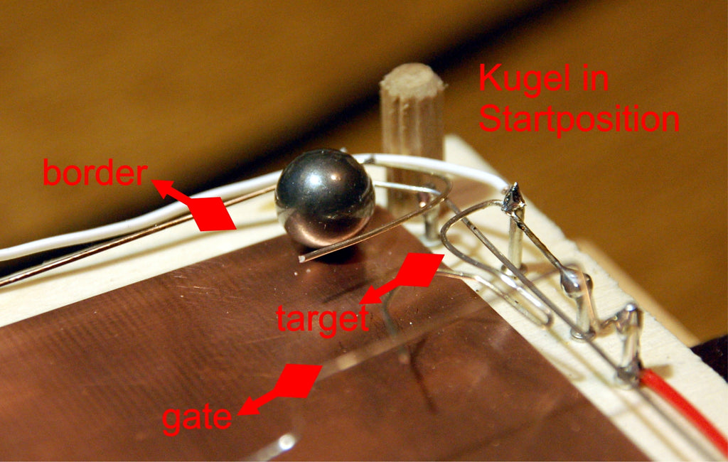
Figure 8: Gate-Target and border connections
Solder the cables with the circuit board (GND) and the wire elements. Solve one of the plug strips to the other cable end.
hardware

Figure 9: Joy Ball Wizzard circuit
There is a greater representation Here as a PDF document.

Figure 10: Voltage supply with Buck's Contribe
A maximum voltage of 6V is permitted to supply the servos. This is delivered by the Buck converter, which in turn is supplied by a 12V plug-in power supply. The ESP8266 also gets the 6V on its connection Vin. This is because the ESP8266 Node-MCU V3, as well as the Amica, have an input voltage regulator AMS1117 3V3 on board, which can withstand tensions up to a maximum of 20V. This voltage controller also supplies the rest of the circuit on the 3.3V output of the ESP8266.
The PCA9685 can supply up to 16 servos or LEDs with PWM signals. The frequency for all connections is the same and can be set between 40Hz and 1 kHz. Communication between PCA9685 and the ESP8266 takes place via the I2C bus. The module pca9685.py Contains the Servo class. It provides all methods that are necessary to control the PWM outputs.
The servos and possible LEDs are plugged directly to the 16 outputs. So that repercussions are largely suppressed to the ESP8266, the PCA9685 module should receive its own 6V and GND from the voltage converter. Not a bad idea is also an ELKO of 470µF/ 16V on the plug or on the green luster clamp on the board.
The OLED display is also on the I2C bus. She informs about upcoming user actions and the score.

Figure 11: Game display
The digital inputs of the ESP8266, which can be used for our purpose, are connected to the joystick button (GPIO0 = D3) and the sensor inputs of the game board. Surrounding (border GPIO12 = D6), obstacles (Gate GPIO14 = D5) and target clip (Target GPIO13 = D7). D4 = GPIO2 is reserved to release the outputs of the PCA9685. The output also operates the LED on the ESP8266 board. So it shines when the servos are released because it is a low-active LED. Optionally, an external LED with a suitable resistance (approx. 1 kΩ) can also be connected to 3.3V (not shown in the circuit diagram). D0 and D8 divide due to system -related peculiarities.
In order to bring the tension level of the joystick to the ESP8266, I use an ADS1115 AD converter module. It delivers up to four 16-bit ADC values of good accuracy and linearity. It is also addressed via I2C. Two inputs, A0 and A1, are required for the joystick, A2 monitors the level of the 6V voltage.
As a joystick, two variants are possible: the simple module Ky-023, or more comfortable Arduino-Shield With 6 buttons.

Figure 12: Joystick mounted on floor slab
The software
For flashing and the programming of the ESP32:
Thonny or
Used firmware for the ESP8266/ESP32:
Please choose a stable version (ESP8266 with 1MB Version 1.18 Status: 05.03.2022)
The micropython programs for the project:
pca9685.py: Module with the Servo class, PCA9685 driver
ads1115.py: Module ads1115; ADS1115 driver
SSD1306.PY: Oled driver
oled.py: OLED class
servo_test.py: Servo test program
Test_Joy.py: Joystick test program
test_oled.py: OLED test program
Micropython - Language - Modules and Programs
To install Thonny you will find one here detailed instructions (English version). There is also a description of how that Micropython firmware (As of 05.02.2022) on the ESP chip burned becomes.
The test programs
First of all, after flashing the firmware, we should search for an AccessSpoint, because, in my experience, this leads to a different way to the module.
On the command line of Thonny we enter the following command and then "D" for "disable". This action should be done every time (only once) according to the flash of the firmware.
>>> Import webrepl_setup
WebRepl Daemon Auto-Start Status: Disabled
Could you like to (e) nable or (d) isable it running on boot?
(Empty line to quit)
> D
No Further Action Required
For the tests of mechanics and hardware, the drivers for the PWM and ADC module, the OLED driver SSD1306 and the OLED module must first be uploaded to the flash of the ESP8266.
pca9685.py: Module with the Servo class, PCA9685 driver
ads1115.py: Module ads1115; ADS1115 driver
SSD1306.PY: OLED driver
oled.py: OLED class
Please download the files into your working directory (AKA WorkSpace). Navigate there in Thonny. Right click on the file opens the context menu. With Upload to / Start the process.

Figure 13: Start upload
Repeat the process for the three other files.
OLED test
Let's start with the test of the OLED display. This happens with the help of the file test_oled.py. We start with some imports. The module oled.py Imported SSD1306.PY. Because this is needed for no further actions directly in the main program, that's okay.
We already initialize the I2C bus in the main program because we also need it for other purposes. As a comment, the Pintranslator relates the Arduino calls to those of espressif. The latter are used by Micropython.
#pca_first.py
# Import webrepl_setup
#> D FUR DISABLE
# Then RST; Restart!
import OS,sys # System and file instructions
from machine import Pin code, reset, I2C
from time import sleep, Ticks_ms
from OLED import OLED
import ESP
ESP.Osdebug(None)
import GC
GC.collect()
# Pintranslator for ESP8266 boards
# Lua-Pins D0 D1 D3 D4 D5 D6 D7 D8
# ESP8266 Pins 16 5 4 0 2 14 12 13 15
# SC SD
sclpine=Pin code(5)
Sdapin=Pin code(4)
I2C=I2C(scl=sclpine,sda=Sdapin,freq=400000)
D=OLED(I2C,128,32)
D.writer("Hello World!",0,0)
sleep(2)
D.writer("Ola Muchachos!",0,1)
D.hine(0,24,127,1)
D.show()
sleep(2)
D.clearall()
D.writer("BUT...",0,1)
sleep(2)
D.hine(0,24,127,1)
D.writer("Hello World!",0,0,show=False)
sleep(2)
D.writer("Ola Muchachos!",0,1,show=True)
sleep(2)
D.clearall()
We hand over the pins declared for SCL and SDA to the constructor of the I2C class together with the value of the operating frequency of 400kHz. In the next episode there is still precise information via the protocol on the I2C bus.
With the I2C object we instantiate the display object D. The OLED class inherits the classroom of the class SSD1306_I2Cthat in turn from the module framebuf the class Frame buffer has inherited. The bottom line is that all methods of the three classes are equal under the Scope from D Are available. However, there is a small difference between the methods of the OLED class and the methods of the other two classes SSD1306_I2C and Frame buffer.
The writing methods of OLED own an optional parameter showthat is set to true by default. This means that every writing access to the display becomes visible immediately. That takes time, because this shovels the entire frame buffer content to the display. And that's why it is better in time -critical situations show = false First to fill the buffer with all the writing actions and only finally carry out the transfer of the buffer to the display.
In the first part of the edition, the texts and the line appear immediately according to the command. The line, as a method call from Framebuffer, only appears after calling up show().
In the second part, the three commands only fill the frame buffer. Only through that show = true the display is transmitted to the display and the display.
Now just test it yourself. Download the program test_oled.py In Thonny by double -clicking from the workspace to an editor window and start with the F5 function key.
In the end I inserted two sequences that show a striking difference in the term. In the first part, a show () calls is made after each output command, in the second part only at the end.
begin=Ticks_ms()
D.writer("Immediate show ...",0,1)
D.hine(0,24,127,1)
D.show()
D.writer("Hello World!",0,0)
D.writer("Ola Muchachos!",0,1)
D.clearall()
runtime=Ticks_ms()-begin
print("Runtime Immediate:",runtime,"MS")
begin=Ticks_ms()
D.writer("BUT...",0,1,False)
D.hine(0,24,127,1)
D.writer("Hello World!",0,0,show=False)
D.writer("Ola Muchachos!",0,1,show=True)
D.clearall()
runtime=Ticks_ms()-begin
print("Runtime Once:",runtime,"MS")
The issue in the terminal does not require any comments.
This is the Constructor of Oled Class
Size: 128x32
Runtime Immediate: 193 MS
Runtime Once: 79 ms
Joystick test
Two adjustable resistors are installed in the joystick, the ends of which are at +VCC = 3.3V and on GND. The grinding contact therefore takes off as voltage parts between 0V and 3.3V. We lead these tensions to the analog digital converter (AKA ADC) on channel 0 and 1.
However, the ADC does not provide us with a voltage value, but a numerical value between 0 and 32767 (we only use the positive area). This results from a counter that runs along, while a comparison voltage is gradually increased in the ADC module. The counter stops when comparison voltage and external voltage are the same.
Now, by noise on the signal line and tolerances, there are always small deviations from one measurement value to the next when changing. The fluttering of the measured values bothers us because it leads to trembling movements of the servo. That is why we only use the highest 12 of the effective 15 bits of the positive voltage area of the ADS1115, with which the PCA9685 can also do something.
One possibility would be to simply push the measured value by 3 bit positions to the right, then the lowest 3 bits fall into the Nirvana and with the rest we feed the servo driver. But we go one step further. More on that after the test.
Download the program for this Test_Joy.py In an editor window and start it. We already know the opening credits. Using the I2C object I2C we instantiate the ADS1115 object joy. The ADS1115 module is located on I2C hardware address 0x48. The Switch We put the joystick on the pin Gpio0, which we define as an entrance with pull-up resistance.
#pca_first.py
# Import webrepl_setup
#> D FUR DISABLE
# Then RST; Restart!
import OS,sys # System and file instructions
from machine import Pin code, reset, I2C
from time import sleep, Ticks_ms
from ads1115 import Ads1115
import ESP
ESP.Osdebug(None)
import GC
GC.collect()
# Pintranslator for ESP8266 boards
# Lua-Pins D0 D1 D3 D4 D5 D6 D7 D8
# ESP8266 Pins 16 5 4 0 2 14 12 13 15
# SC SD
sclpine=Pin code(5)
Sdapin=Pin code(4)
I2C=I2C(scl=sclpine,sda=Sdapin,freq=400000)
joy=Ads1115(I2C,0x48)
SW=Pin code(0,Pin code.IN,Pin code.Pull_up)
while 1:
joy.setcannel(0) #
X=joy.GetConvresult()
joy.setcannel(1) #
y=joy.GetConvresult()
print(X,y)
sleep(1)
IF SW.value()==0:
break
while 1:
joy.setcannel(0)
X=joy.transform((-joy.GetConvresult()),-28200,0,0,4096)
joy.setcannel(1)
y=joy.transform((-joy.GetConvresult()),-28200,0,0,4096)
print(X,y)
sleep(1)
IF SW.value()==0:
break
In the first While loop, we place the entrance to the ADS1115 to channel 0 and call the conversion result. We do the same with channel 1. We have the values out in the terminal and wait a second.
The measured values are positive, because of the basic settings of the ADS1115 (Unipolar up to 4.096V), it was not to be expected otherwise during instantiation. But the small values come when the control stick is pressed to the right or from us, i.e. to the rear. That is unfavorable, conversely it would be better.
We regulate this with the method transform() from the ADS1115 class. First we make the measured value negative. We almost reflect the joystick. But we cannot need negative values and that's why we let ourselves be used by the method transform() map the value range from -28000 to 0 to area 0 to 4096. There is a method of this kind in Lua-Nodemcu (match) but not in Micropython. So I made it myself.
A pressure on the joystick ends the first part. In the second while loop, we receive values in the usable area and in the desired assignment to the movement of the control stick. By changing the transformation target values, we can also even adjust the result range. Try the following settings:
     X=joy.transform((-joy.GetConvresult()),-26500,0,0,4096)
     y=joy.transform((-joy.GetConvresult()),-26500,0,0,4096)
or
     X=joy.transform((-joy.GetConvresult()),-26500,0,260,2350)
     y=joy.transform((-joy.GetConvresult()),-26500,0,500,2100)
The servo test
The test program for the servos only needs a little more than the program Test_Joy.py. We instantiate the servo object servo By handing over the I2C object I2C and the optional parameter oe, which defines the GPIO2 as a control output for activating the outputs of the PCA9685. The optional parameter freq is not listed why the default value 50 becomes effective.
#pca_first.py
# Import webrepl_setup
#> D FUR DISABLE
# Then RST; Restart!
import OS,sys # System and file instructions
from machine import Pin code, reset, I2C
from time import sleep, Ticks_ms
from PCA9685 import Servo
from ads1115 import Ads1115
import ESP
ESP.Osdebug(None)
import GC
GC.collect()
# Pintranslator for ESP8266 boards
# Lua-Pins D0 D1 D3 D4 D5 D6 D7 D8
# ESP8266 Pins 16 5 4 0 2 14 12 13 15
# SC SD
sclpine=Pin code(5)
Sdapin=Pin code(4)
I2C=I2C(scl=sclpine,sda=Sdapin,freq=400000)
oepin=Pin code(14,Pin code.OUT)
servo=Servo(I2C,oe=2)
joy=Ads1115(I2C,0x48)
while 1:
joy.setcannel(0)
X=Max(min(joy.GetConvresult()>>3,3400),0)
pulsex=joy.transform(-X,-3400,0,300,2100)
joy.setcannel(1)
y=Max(min(joy.GetConvresult()>>3,3400),0)
pulsey=joy.transform(y,0,3400,350,2350)
servo.Write PulseTimeslice(4,0,pulsex)
servo.Write PulseTimeslice(7,0,pulsey)
print(X,y,"--",pulsex,pulsey)
To read in the channels and the transformation of the values, follow the servos in the While loop instead of the output of the values. It is an experience when the stages at the gaming table suddenly start to rock and rock.
Usually there is a noise level on the analog input cables that the ESP8266 produces itself or that comes from the electrosmog in the area. After the AD conversion, the bird-playing change of the low-quality areas of the converter values is expressed. This has to be suppressed. For this reason, I also chose a converter with a resolution of 16 bits. Positive signals up to 4.096V are implemented with 15-bit width on values from 0x0000 to 0x7fff. If I now send the lower 3 bits to Nirvana by pushing the converter value by 3 binary points to the right, I still have 12 bit resolution and the noise is filtered out.
I now enter the converter values to 0 to 3400. This is the area that I can specify with the joystick. Then I take the values with me transform() in such a way that the limit values result in an average in which the respective soil lies horizontally and the ball remains in peace.
In the next episode, you can see how a game can be programmed with all of these preparations. Then we will also take a closer look at the PCA9685 class and study the behavior of the PCA9685 chips. Now I wish you a lot of fun trying the infrastructure and fine tuning. Until then!


