In this series of articles, I am addressing my colleagues in the physics department. The next episodes will focus on a force gauge without a coil spring, which naturally requires the use of an elastic sensor. However, very little of its elasticity is visible. Nevertheless, the barely perceptible visual aspect does not detract from the resolution, but rather enhances it. I will reveal how this is possible in the new episodes of the series.
MicroPython on the ESP32, ESP8266, and Raspberry Pi Pico
today
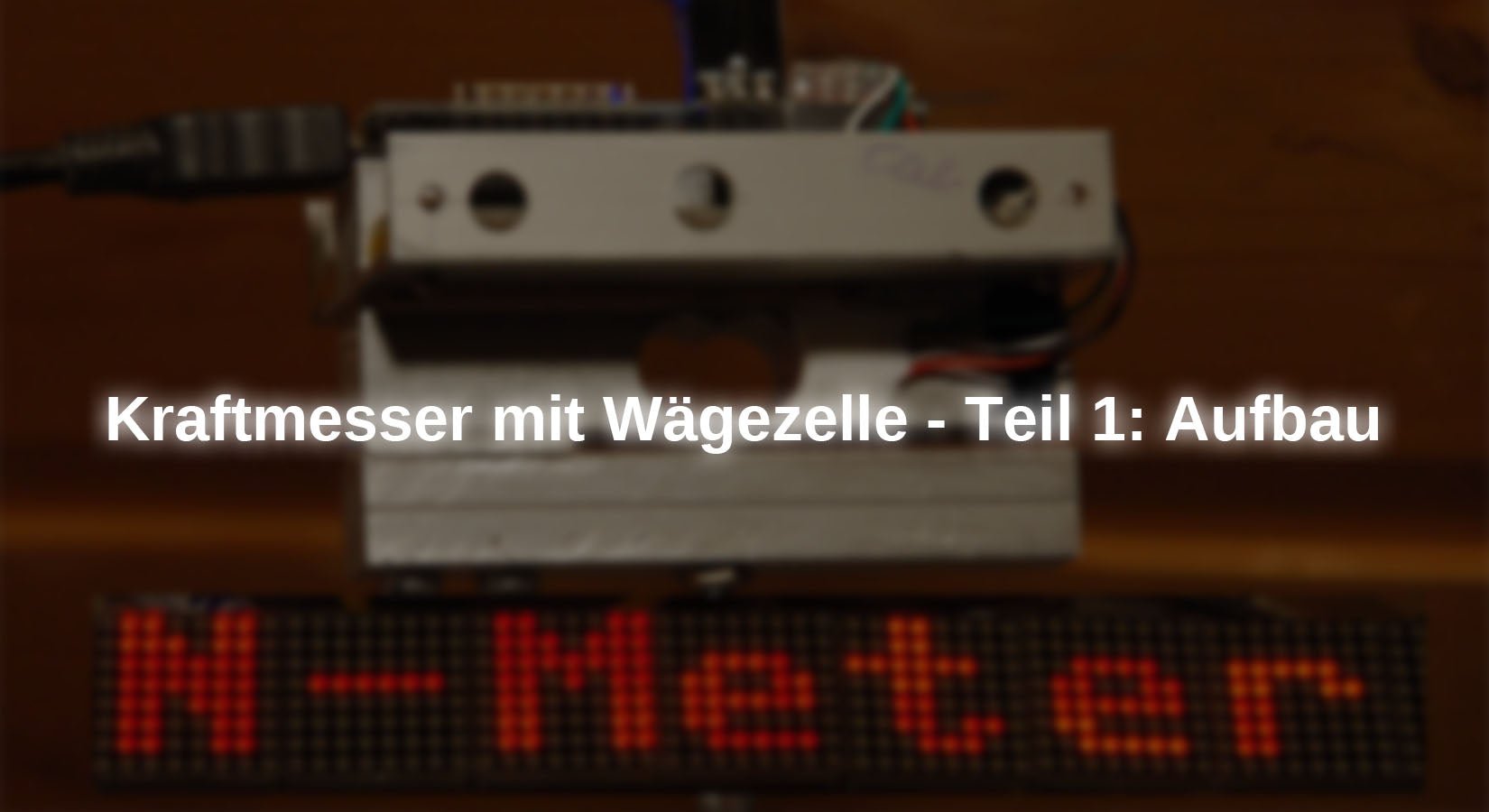
A force gauge under MicroPython – Part 1
1. In the first part, we will look at the measuring principle and the hardware design.
2. In the second part, we add a large display to the laptop, which is controlled via USB.
3. In Part 3, we replace the USB data cable with wireless transmission.
4. Part 4 includes a display unit with 8 LED panels, which is also connected via Wi-Fi.
5. An Android tablet as a display unit is presented in Part 5.
The force sensor
Some time ago, I used a component, from the same family as the one now being used again, in another Libra installed. In both cases, it is ultimately a matter of measuring forces. This means that even when determining mass with a scale, the aim was to measure a force, namely the gravitational force F.gThis is linked to the mass m of weighing pieces via the location factor g = 9.81 N/kg: Fg = g • m. This made it possible to calibrate the scales using weights. Figure 1 shows such a weighing beam. The right side of the scales is screwed firmly to the base, while the weighing pan is attached to the left side.

illustration 1Load cell from the side
In the current case, the aim is to measure forces directly. This is made possible by the elastic deformation of an aluminum weighing beam to which strain gauges are attached. These components consist of extremely thin conductor loops which, depending on their position, are stretched or compressed by the bending of the thinned sections of the beam, thereby changing their electrical resistance.

illustration 2: Schematic representation of strain gauges
Stretching makes conductors longer and thinner, while compressing has the opposite effect. Conductor length and cross-sectional area are both factored into the calculation of a conductor's electrical resistance. Both lengthening and reducing the cross-sectional area increase the resistance value. ρ is the specific resistance, a material constant.

illustration 3: Resistance formula
To ensure that even the smallest changes in resistance value result in a reproducible measurement result with high resolution, the measuring strips are combined into a bridge circuit, whose output voltage is fed to a precision amplifier. The output voltage of this amplifier now only needs to be digitized for processing in a microcontroller.

illustration 4Strain gauges on the HX711
The HX711 module contains both components and also allows the gain to be selected: 128x or 64x at differential input A and 32x at input B. The transmission of the 24-bitADC-value (ADC = Analog Digital Converter) to the microcontroller is done via the Data-Line, which is activated by 24 pulses at Clock Up to three additional pulses influence the gain setting of the PGA (Programmable Gain Amplifier) for the next measurement. The weighing beam used here can be loaded with up to 5 kg, which corresponds to a maximum force of approx. 50 N. Together with input A and gain=128, we achieve a resolution of 1 mN, corresponding to approximately 0.1 grams of mass. Because this is already the point of uncertainty, we are satisfied with 10 mN as the smallest measured variable and obtain a stable measured value display in return. 0.01 N is also far more than can be achieved with force gauges with coil springs.

illustration 5: Gain adjustment via additional clock pulses
The software interface to the HX711 is the HX711 class from the MicroPython module hx711.py. We will come back to this later.
hardware
Any ESP8266 or ESP32 model with at least four free GPIOs is suitable as a controller. The measured value is initially shown on an OLED display. Of course, a different model can also be used as a load cell. They are available with weighing capacities ranging from 100g up to 100kg and more.
For reasons of space, I opted for a D1 Mini NodeMcu with ESP8266-12F WiFi module Decided. For the time being, the measuring electronics will be powered via USB.
|
1 |
D1 Mini NodeMcu with ESP8266-12F WiFi module or D1 Mini V3 NodeMCU with ESP8266-12F or NodeMCU Lua Amica Module V2 ESP8266 ESP-12F WIFI or NodeMCU Lua Lolin V3 Module ESP8266 ESP-12F WIFI or ESP32 Dev Kit C V4 unsoldered or ESP32 NodeMCU Module WLAN WiFi Development Board with CP2102 or |
|
1 |
|
|
1 |
NeoPixel LED from strip WS2812B 30 LEDs/m 30 pixels/m LED strip RGB addressable LED strip with 5050 SMD LEDs IP20 Black Not waterproof |
|
1 |
|
|
1 |
HX711 AD converter for load cells |
|
1 |
|
|
2 |
Button from the range Microswitch Push Button Set - 180 Pieces, Various Sizes, Versatile Push Buttons for Electronics |
|
various |
Jumper wire cable, 3 x 40 pcs., 20 cm each, M2M/F2M/F2F possibly also |
|
1 |
Mini breadboard 400 pins with 4 power rails for jumper cables |
|
4 |
Screw M4 x 25 |
|
4 |
M3 x 7 screw |
|
4 |
M3 x 10 screw |
|
2 |
Screw eye M4 x 40 |
|
2 |
Spacer plates 21 mm x 12 mm x 2.5 mm |
|
2 |
Aluminum profile 12 mm x 12 mm x 75 mm |
|
2 |
Aluminum U-rail 15 mm x 13 mm x 75 mm; t = 1.5 mm |
|
4 |
Plexiglass pane 12 mm x 10 mm x 2 mm |
|
optional |
The circuit for the ESP8266 D1 Mini

illustration 6Force gauge - Circuit
The software
For flashing and programming the ESP32:
Thonny or
Creating your own character sets
zeichensatz.rar Work environment for creating your own character sets
For displaying bus signals
SALEAE – Logic analyzer software (64-bit) for Windows 8, 10, 11
Firmware used for the ESP32:
Firmware used for the ESP8266:
Firmware used for the Raspberry Pi Pico (W):
RPI_PICO_W-20240602-v1.23.0.uf2
The MicroPython programs for the project:
ssd1306.py Hardware driver for the OLED display
oled.py API for the OLED display
geometer_30.py Large character set for the numeric display
hx711.py API for the AX711
newtonmeter.py The operating program
MicroPython - Language - Modules and Programs
For instructions on installing Thonny, please refer to the following link: detailed instructions (English version). It also includes a description of how the Micropython firmware (as of January 25, 2024) on the ESP chip burned will be. You can find out how to get the Raspberry Pi Pico ready for use here here.
MicroPython is an interpreted language. The main difference to the Arduino IDE, where you always and exclusively flash entire programs, is that you only need to flash the MicroPython firmware onto the ESP32 once at the beginning so that the controller understands MicroPython instructions. You can use Thonny, µPyCraft, or esptool.py for this. For Thonny, I have the process here described.
Once the firmware has been flashed, you can easily communicate with your controller, test individual commands, and see the response immediately without having to compile and transfer an entire program first. That's exactly what bothers me about the Arduino IDE. You save a tremendous amount of time when you can test the syntax and hardware in advance, try out and refine functions and entire program sections via the command line before you start writing a program. For this purpose, I like to create small test programs. They act as a kind of macro, combining recurring commands. These program fragments can then be used to develop entire applications.
auto start
If you want the program to start automatically when the controller is switched on, copy the program text into a newly created blank file. Save this file as main.py in the workspace and upload it to the ESP chip. The program will start automatically the next time the device is reset or switched on.
Testing programs
Programs are started manually from the current editor window in the Thonny IDE by pressing the F5 key. This is faster than clicking the Start button or using the menu. RunOnly the modules used in the program must be located in the ESP32's flash memory.
Back to Arduino IDE again?
If you want to use the controller with the Arduino IDE again later, simply flash the program in the usual way. However, the ESP32/ESP8266 will then have forgotten that it ever spoke MicroPython. Conversely, any Espressif chip that contains a compiled program from the Arduino IDE or the AT firmware or LUA or ... can easily be equipped with the MicroPython firmware. The process is always the same as here described.
Setup of the measuring device
To suspend the weighing beam measuring 12 mm x 12 mm x 75 mm, we need two additional aluminum profiles with the same dimensions, as well as two aluminum sheets measuring 21 mm x 12 mm x 2.5 mm to serve as spacers. Two aluminum U-rails are needed to hold the circuit boards on which the controller and the HX711 are mounted. Here is the parts sketch, which is also available as a PDF document downloaded can be found. It contains the layout of the circuit boards and their assembly plan.
I got the aluminum profiles at the hardware store. M3 threads had to be cut into the upper profile to attach the U-rails. The circuit boards are also attached to the U-rails using M3 threads and Plexiglas spacers (12 mm x 10 mm x 2 mm). 3 mm threads on the outer sides of the U-rails are used to attach an optional cover.

illustration 7Mechanical design of the force gauge

illustration 8: Sensor unit from above

illustration 9Force gauge in use
Figure 8 shows the assembly of the electronics. Two circuit boards serve as carriers, which are equipped with socket strips for mounting the microcontroller and HX711. Here are the layout and assembly plan. Three cable connections are marked in green.

illustration 10Layout of the two circuit boards
For the first trial run, I set up a test setup with a NodeMCU Lua Lolin V3 Module ESP8266I used whatever was at hand. I connected the weighing beam to the circuit with my test cables.

illustration 11Test setup with an ESP8266 Node MCU board
These test cables can be easily made from a highly flexible silicon cable and one test terminal in any length. A single-pole connector strip allows connection to the breadboard. A piece of heat-shrink tubing contrary to.

illustration 12: Practical test clamp with silicone cable
A large character set for the OLED display
Large digits make it much easier to read the measurement. Instead of the usual eight pixels, we use 30 pixels as the character height. The file geometer_30.py contains the relevant information.
To create our own character set for the OLED display, we need a few ingredients.
1. Python for Windows
2. freetype-py
If Python is not yet installed on your PC, you must do so now. Download the latest package Python 3.13.3 and install it by running the file python-3.13.3-amd64.exe Start it in the download folder and follow the wizard.
freetype-py is a tool required by Windows for converting a TTF font set. Python also includes a tool called pip3 installed. We use this to freetype-py to install.
Open the command prompt and enter the following line at the prompt.
pip3 install freetype-py
Here's how to create your own font set from the TTF font library in Windows.
Download the archive zeichensatz.rar and unzip the contents into any directory. To save typing, I recommend a directory with a short name in the root path of the hard drive or a USB stick. For me, it is F:\fonts.
Open a Powershell window in this directory from Explorer by holding down shift key one right-click on the directory. Then left-click on Open PowerShell window here.

illustration 13Open Powershell window
At the prompt, enter the following line and press Enter.
.\makecharset.bat geometer 30 """0123456789,-+N""" "F:\fonts\sources\"

illustration 14The character set is ready.
There is now a file in the directory geometer_30.py with the pixel data of the new character set extract. Only the characters in """0123456789,-+N"""This saves storage space. You can download additional character sets from the fonts-directory of Windows to the directory sources Copy and convert as described above. Please note that the file name is specified without the extension .TTF.
We now copy the generated character set to the working directory of our new MicroPython project.
Initial tests
The signal LED
Then we can start running a few initial tests. To do this, we can use the test circuit shown in Figure 11, to which the weighing beam is connected as shown in the circuit diagram in Figure 6.
For the signal LED, I used a Neopixel LED from an LED strip that was left over from building the abacus clock. This has the advantage that any color can be displayed with a single LED via a single control line.
illustration 15: Neopixel LED
Because the NodeMCU Lua Lolin V3 Module ESP8266 Since the 5V from the USB is not output at the Pin Vin, I connected +5V of the strip to the 3.3V output of the controller board, which works fine with an LED. The ESP8266 D1 MiniThe sensor we install in the force sensor actually supplies the 5V from the USB at the 5V pin. din we connect D4 = GPIO2 on.
The following section describes entries in REPL bold formatted, output italic.
>>> from neopixel import NeoPixel
The Neopixel object consists of an LED on GPIO2.
>>> led=Pin(2, Pin.OUT, value=0) # D4
>>> np=NeoPixel(led,1)
We define some colors...
>>> red=(4,0,0)
>>> blue=(0,0,4)
>>> yellow=(16,8,0)
>>> off=(0,0,0)
And check their effectiveness.
>>> np[0]=red
>>> np.write()
>>> np[0]=off
>>> np.write()
We summarize color selection and writing to the LED in the function signal() together.
def signal(col):
np[0]=col
np.write()
>>> signal(yellow)
>>> signal(off)
Measurement of forces
For operating the HX711 Is there a class in the module hx711.py lives. If you start hx711.py in a Thonny editor window, then the if block at the end of the listing creates an HX711 object with the identifier hx.
if __name__ == "__main__":
from machine import Pin
hx=HX711(Pin(14),Pin(12,Pin.IN)) # D5, D6
This allows us to take our first steps with the force sensor. We retrieve a measured value, as determined by the HX711, via the serial line. According to its circuitry, we receive 10 values per second (connection rate = GND).
>>> %Run -c $EDITOR_CONTENT
HX711 ready on channel A with gain 128
>>> hx.getRaw()
-502747
This value is obtained for the unloaded weighing beam. In our case, the reference point is not the lower mounting bracket of the weighing beam, but the hook in the upper part. When the measuring unit is suspended, the load-bearing parts of the sensor also include the profile parts mounted below the weighing beam. We must take this value into account as tare for later measurements. We determine the tare value as the average of several measurements. We specify the number of measurements when calling up the function, in this case 2.
>>> hx.tara(2)
-502631

illustration 16: Record tare weight
Next, the sensor must be calibrated. This means that the raw measurement value for a specific force, corrected by the tare value, must be converted into a force value in newtons. So we clamp the weighing beam securely in place or hang up our measuring unit, start hx711.py, and call hx.tara(2) The tare value is thus stored in the attribute hx.tare stored and returned.
Now we need to determine the calibration factor for conversion to newtons. This is done using the method hx.calibrateF(), to which we transfer the mass of 102g. In the Earth's gravitational field, a weight force of approx. 1 Newton acts on this mass, depending on the measurement location.

illustration 17Calibrate to 1N with a mass of 102g.
This value is also used as an attribute. hx.fcal of the HX711 object. From now on, we can measure forces directly by using the method hx.power(n). The parameter n indicates the number of measurements to be performed, from which the average value is calculated. Each individual measurement takes approximately 100 ms.
>>> hx.calibrateF(102)
44098.7
>>> hx.force(2)
1.00366
We can retrieve the calibration factor at any time and manually readjust it if necessary. To simplify the procedure, it is recommended to store the calibration factor found in the class. HX711 for the class attribute KfactorForce Alternatively, we could also write the value to a file that we read every time we boot up.
>>> hx.fcalFactor(44098.1)
>>> hx.force(2)
1.00045
>>> hx.force(2)
1.00288
We recognize that a usable result can only be given to two decimal places, because the third decimal place is already significantly unstable. However, this is sufficient, because no conventional force gauge with a coil spring can resolve to 0.01 N. In future, we will therefore trim our measurement results to six digits with two decimal places for display and output them right-aligned (>) with an "N" as the designation.
>>> "{:>6.2f} N".format(hx.force(2))
' 1.00 N'
Larger characters on the OLED display
The module geometer_30.py has the following structure. After a header listing the characters contained, the height, and the maximum width of the characters, the list continues with number tuple, whose first component specifies the current character width. This is followed by the pixel pattern of the character in the form of bytes-Objects in binary representation. About the position of the character in the string characters we gain access to the entry in number. Custom characters can be generated by manually creating the bit pattern and inserting a pointer character in characters enter.
The module must be uploaded to the controller's flash memory so that it can be accessed.
>>> import geometer_30 as cs
Imported in this way, we can import the module without the prefix surveyor_30 very briefly with the prefix cs address.
chars="0123456789,-"
height=31
width=29
number=[
(17, # Characters: 0
0b00000000000000000,
0b00000000000000000,
0b00000000000000000,
0b00000011111000000,
0b00001111111110000,
0b00011111111111000,
0b00011111111111000,
0b00111110001111100,
0b00111110001111100,
0b01111100000111110,
0b01111100000111110,
0b01111100000111110,
0b01111100000111110,
0b01111100000111110,
0b01111100000111110,
0b01111100000111110,
0b01111100000111110,
0b01111100000111110,
0b00111110001111100,
0b00111110001111100,
0b00011111111111000,
0b00011111111111000,
0b00001111111110000,
0b00000011111000000,
0b00000000000000000,
0b00000000000000000,
0b00000000000000000,
0b00000000000000000,
0b00000000000000000,
0b00000000000000000,
0b00000000000000000,
),
To display this, we now simply need to set a pixel in the display at every position where there is a 1 in the pattern, starting from the starting position (= upper left corner of the character matrix). This is done by the function putNumber(). We obtain the number of the pattern in the list from the following line. z is the sign to be represented, the method index() determines the position in characters.
>>> n=cs.chars.index(z)
def putNumber(n, xpos, ypos, show=True):
width=cs.number[n][0]
for row in range(1, cs.height):
for col in range(width-1,-1,-1):
c=cs.number[n][row] & 1<
d.setPixel(xpos+width+3-col,ypos+row,c,False)
if show:
d.show()
return xpos+width+2
We retrieve the character width and scan the pattern line by line and column by column. We read the color code c, 0 or 1, and set the pixel to the background or foreground color, 0 or 1, accordingly (false). Two pixels are provided as character spacing. The function returns the x-position for the next character so that characters can be displayed in proportional mode.
For the next tests, the files must be oled.py and ssh1306.py be uploaded to the controller's flash memory.
>>> import geometer_30 as cs
from machine import Pin, freq, SoftI2C
>>> from oled import OLED
>>> import geometer_30 as cs
def putNumber(n, xpos, ypos, show=True):
width=cs.number[n][0]
for row in range(1, cs.height):
for col in range(width-1,-1,-1):
c=cs.number[n][row] & 1<
d.setPixel(xpos+width+3-col,ypos+row,c,False)
if show:
d.show()
return xpos+width+2
>>> n=cs.chars.index("5")
>>> n
5
>>> n=cs.chars.index("N")
>>> n
13
>>> d.clearAll(False)
>>> pos=putNumber(5,0,0, False)
>>> pos=putNumber(13,pos,0, True)
We now have everything we need to program our force gauge. We will implement this in the next article.
So stay tuned! See you then!


2 comments
Claus
Hallo,
toller Artikel, musste ich gleich aufbauen.
Wenn ich die Firmware flashe und alle Dateien vom Abschnitt “Die MicroPython-Programme zum Projekt” auf den ESP schreibe bekomme ich nach Programmstart die Fehlermeldung:
this is the constructor of OLED class
Size:128×32
HX711 bereit auf Kanal A mit Gain 128
HX711 initialisiert nicht
Wenn ich hingegen das Script hx711.py vom Bereich “Messung von Kräften” starte (die Zeile “from timeout import TimeOutMs” musste ich auskommentieren, da das Modul nicht gefunden wurde) bekomme ich sinnvolle Messwerte, die sich deutlich ändern, wenn ich das Gewicht ändere.
Was mache ich falsch?
DAVY
Bonjour!
Article clair, explicite, et remarquable parmi les autres: On a: Principe physique + Hard + Soft +Expérimentation !! Et chacun tour à tour explicités ! Belle pédagogie.
Félicitations et merci pour le partage.
En attendant impatiemment la suite ….