No typing error, not i2c (or i²C = inter-integrated circuit), but actually i2s (or i²s = inter-ic sound).
This is a serial interface also developed by Philips, but only for the transfer of digital audio data.
Looking for possible new products for the range of AZ-Delivery I came across a small breakout board called "Max98357 Amplifier Breakout Interface I2S Class D Module for ESP32 Raspberry Pi".
In the meantime, the parts are in the range of AZ-Delivery accessible. Hence the list of hardware used here:
|
1 |
Raspberry Pi, e.g. 3 B+ |
|
2 |
|
|
2 |
|
|
1 |
(Mini)-Breadboard, jumper cable |
Back to the first attempts. As always with orders from the Far East, I prepared for a delivery time lasting several weeks and searched for further support such as circuit diagram, program library, and demo program elsewhere on the Internet. And found: As so often with the colleagues from Adafruit, who sell an identical board.
On the Adafruit page, I found, among other things, the explanation of why only ESP32 and Raspberry Pi stand for the product name of the Max98357 board: the microcontrollers with Atmega328 have no i2S interface. I choose the first attempts for the Raspberry Pi and follow the Instructions From Lady Ada and her team, who unfortunately is no longer very topical, but still helps me well.
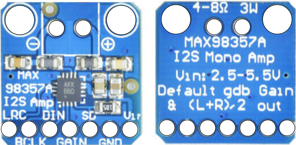
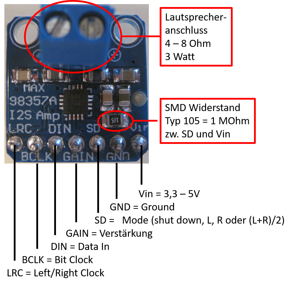
On the small breakout board, the terminal block for the loudspeaker connections and a seven-pin pin bar are soldered.
Important NOTE: Exit not Switch to an amplifier input! Connection only for speakers with 4 to 8 ohms, the output power is approx. 3 watts.
Connection to the Raspberry Pi with 2x20 J6 header as follows:
Vin to pin 2 (5V) for maximum output power
GND on pin 6
DIN to GPIO 21 (PIN 40)
BCLK to GPIO 18 (PIN 12)
LRC to GPIO 19 (PIN 35)
The connections for gain and SD initially remain unaffected. The default settings are then gain = 9 dB, loudspeaker output (L+R)/2, i.e. both stereo channels as a mono output.
In order to activate the I2S interface, we have to make some additions and changes to the Raspberry Pi OS. There is no choice in the configuration menu for the other interfaces. Instead, the sub-directory / boat / the file config.txt is edited, of course with superuser rights.
sudo nano /boot/config.txt
In this editor, you cannot work with a click of the mouse, but for me, the scroll wheel worked. Otherwise with the cursor keys click up to the line
dtparam=audio-on
This line is commented on. Then we add
#dtparam = audio-on
dto -losing=Hifiberry DAC
dto -losing=I2S-MMAP
With Ctrl + O and we save the file config.txt, with Ctrl + X Let's end the editor.
After that, the Raspberry Pi has to be restarted, e.g. with
sudo reboot
If we right-click on the loudspeaker symbol, the options for the sound output are displayed, before the changes HDMI and AV Jack, and after the changes HDMI and snd_rpi_hifiberry_dac. When we select the HiFiberry, the music comes from the loudspeaker on the Breakout-Bord Max98357a if everything is properly connected.

Here are two screenshots from the Raspberry Pi, the first is the newly designed configuration menu for the interfaces - i2S is not included. Then the text editor Nano with the file config.txt.


Now nothing stands in the way of the first test with a max98357a and mono edition. And - Heureka - it worked right away. We have not yet dealt with the I2S signals in detail.
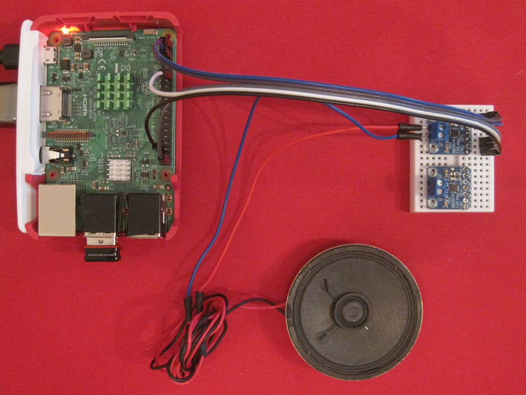
Here is a picture of my test setup with an old PC speaker, the new 3W speakers from AZ-Delivery were unfortunately not yet arrived at the time. In the end, I will report on the quantum leap in sound quality with the new 3W speakers.
So far we had not used two connections but had used the default settings available (default). In the case of Gain, this was a reinforcement of 9 dB. The other options from 3 dB to 15 dB can be reached by connecting the gain connection directly or via a 100 kohm resistance with GND or with VIN. In detail:
- 15db with 100k Resistance Between Gain and GND
- 12DB with gain directly to GND
- 9db if the gain is not connected (default)
- 6db with gain directly to Vin
- 3DB with 100K Resistance Between gain and vin
I have not tried these settings because the other connection irritated me much more:
Labeled with SD, it is more of a selection of fashion, with a voltage below 0.16 V (e.g. connected to GND) the chip/amplifier is located in shutdown (hence the SD), for tensions between 0.16 and 0.77 V are issued both channels (Left + Right)/2. This is the default, since the built-in pull-down resistor of 100 kohm with the SMD resistance of 1 MOHM clearly visible on the breakout board results in tension in this area.
With a voltage at SD between 0.77 V and 1.4 V, the right stereo channel is output, and the left stereo channel is over 1.4 V. Then of course you need two Max98357a modules.
But where do you get the right tension from SD?
For the examination, we start with the two built-in resistors:

With VIN = 5 V, the voltage divider results in a voltage of approx. 0.45 V to SD; This is in the area for (L+R)/2, i.e. the mono output of both stereo channels.
Basically, the voltage divider can only be changed by a parallel resistance between SD and GND or between SD and Vin. A series circuit with built-in resistors is not possible.
To get the shutdown mode, a direct connection of SD with GND is sufficient.
If you want to listen to your music in Stereo, you first need two Max98357a, in which the connections used in the first part are switched on in parallel. Then we switch resistance between SD and VIN, i.e. parallel to the SMD resistance with 1 MOHM. For example, to lay about 1 V, for example, you need approx. 400 kohm for the module with the right channel, for the left channel a resistance of approx. 150 kohm would be suitable so that there is approx. 2 V. According to this overload bill, I am looking for suitable resistances in my range.
With a (measured) 394 KOHM resistance on the right channel, I measure a voltage of 1.2 V, at 153 kohm on the left channel 2.0 V. and I now listen to the music in stereo.


With the following image from the data sheet with the signal course you can see that the LRCLK ratings much slower than that Bitclockto send 16 data bits each either to the right or left channel:

In every English final report, it says: "There is always room for improvement". That also applies here. Weak points in my experimental setup are certainly the bad loudspeakers made of ancient PCs, which in the past should only do BEEP when switching on. And disorders from the power supply could certainly be mitigated with a large capacitor.
All in all, an exciting attempt for me to recreate one of the (expensive) plug-in sound cards with two Max98357a.
After I meanwhile the new parts from the range of AZ-Delivery got the result of the new attempts here. As expected, everything worked out right away. Pin strips and terminal blocks at two Max98357 Amplifier Breakout Interface I2S Class D modules Solidated and replaced in the Breadboard circuit, the new ones 3W loudspeaker Connected and stereo music played with the VLC media player. As I said: a quantum leap in the sound quality, in any case, better than my loudspeaker in the monitor (not to mention the old PC speakers).
Here is a photo of the test setup with the parts from the range of AZ-Delivery:


8 comments
Andreas Wolter
@Manuel: wie Bernd Albrecht bereits per Mail informiert hat, gibt es spezielle I2S Mikrofon-Module.
Grüße,
Andreas Wolter
AZ-Delivery Blog
Manuel
Danke für den Beitrag. Ich frage mich wie man dann z.B. einen Speaker (Mono) und ein Mikrofon verdrahtet mit I2S. Geht das überhaupt?
Holger Kaumann
Hallo,
Danke für die Beschreibung wie i2s für Stereo-Ausgabe verwendet werden kann. Genau danach habe ich gesucht :-)
Bernd Albrecht
Gute Nachrichten für alle ESP32 Fans. Unser eBook-Schreiber hat es hin bekommen. Demnächst hier sein Sketch für Internet-Radio mit I2S.
Bernd Albrecht
@ Dieter: Warum Raspberry Pi und nicht ESP? Weil Programm und Musik-Daten Platz auf der gleichen µSD-Karte haben. Für den ESP bräuchte man einen Kartenleser. Dann kann man aber gleich ein kombiniertes Sound-SD Card-Modul nehmen wie das folgende:
https://www.az-delivery.de/products/wtv020-sound-audio-modul-sd-card-fur-arduino
Wer weitere Informationen wünscht zu I2S auf dem ESP32:
https://docs.espressif.com/projects/esp-idf/en/latest/esp32/api-reference/peripherals/i2s.html
Andreas Wolter
wenn Sie durch den Beitrag inspiriert wurden, fühlen Sie sich frei und nutzen ihn als Vorlage für solche Erweiterungen. Lassen Sie uns gerne wissen, was daraus geworden ist.
Grüße,
Andreas Wolter
AZ-Delivery Blog
Olaf Stolle
Hallo das finde ich total interessant.
Eine Steigerung wäre jetzt noch ein Cam module mit gegen Sprechanlage da würde ich mich sehr drüber freuen.
Dieter
Das gleiche jetzt noch mit dem ESP!