Some time ago I used an ESP32 to set the voltage of a switching regulator module via an LED and a photo resistor (LDR = Light Dependent Resistor). This is feasible and makes sense for higher currents (3A and more), because you don't have to care about the regulator itself. A disadvantage is the slow LDR.

Image 1: MPP finder - structure
But a simple switching converter in the range of small to medium power can also be built by an ESP32 itself. The nice thing is that such a converter can be controlled by different sensors, or even by radio. Depending on the converter type, it can be used to step down or step up DC voltages. Such a circuit and the MicroPython program responsible for it are presented to you today in the first part of the series on this topic. So welcome to a new episode of
MicroPython on the ESP32 and ESP8266
today
ESP32 and switching power supplies
Switching power supplies have to chop a DC current so that the voltage at the input can be converted to a lower or higher voltage at the output. This task of a switch is done by a MOSFET transistor, which we will drive from a PWM output of our controller. Three other components, a diode, an inductor, and an electrolytic capacitor (electrolytic capacitor), then do the rest. So that the coil does not have to be too voluminous, it is necessary to carry out the switching process with higher frequencies.
Unfortunately, the PWM function of the ESP8266 family with a maximum frequency of 1000Hz = 1kHz is unsuitable for the following projects, because here I need 50kHz upwards. This can only be done by an ESP32, which delivers up to 40 MHz. But we don't want to go too high with the frequency, because the pulse length should also be well adjustable. The ratio of pulse length to the period duration of the PWM signal is called the duty cycle. The resolution of the duty cycle decreases with increasing frequency.

Image 2: Frequency, period duration, and duty cycle
For our purposes, two circuits come into question: the boost converter and the buck converter. We will take care of the operation of these modules first.
The boost converter

Image 3: Boost Converter - Principle
While the switch is closed, a current flows through the coil, creating a magnetic field. When the switch is opened, the magnetic field collapses. An induction current now briefly flows in the coil in the same direction as the charging current before. The induction voltage at the coil is superimposed on the supply voltage at the input. The voltage values are added together when battery cells are connected in series. As soon as this voltage becomes higher than the sum of the voltage at the capacitor and the threshold voltage of the diode, a current flows through the diode, charging the capacitor and feeding the load. The voltage at the output is always higher than the supply voltage.
The buck converter

Image 4: Buck Converter - Principle
When the switch is closed, a current flows through the coil and the load, creating a magnetic field. When the switch is opened, the magnetic field collapses. According to Lenz's rule, the induction current flows again in the direction of the charging current, as in the boost converter. The longer the charging current flows through the coil, the more energy is in the magnetic field. When the switch is opened, the coil releases this energy again. However, the induction voltage cannot become higher than the supply voltage.
ESP32 and a field-effect transistor as a switch
Of course, nobody can close and open a mechanical switch 50000 times a second. Therefore, I replace the switch with a power transistor of type IRLZ24, which is an N-channel MOSFET that can handle up to 55V. With this, currents up to 18A can be switched, which is probably good enough for our purposes. But more important than the maximum current in our case is the quite low on-resistance of 0.06 Ohm and the fact that the transistor has a logic level gate. This means that it can be fully controlled by a TTL level of 5V.
Unfortunately, however, the ESP32 only supplies 3.3V, so we need another low-power transistor (BC337) as a driver stage for the buck converter we are building today. Figure 5 shows the circuit.
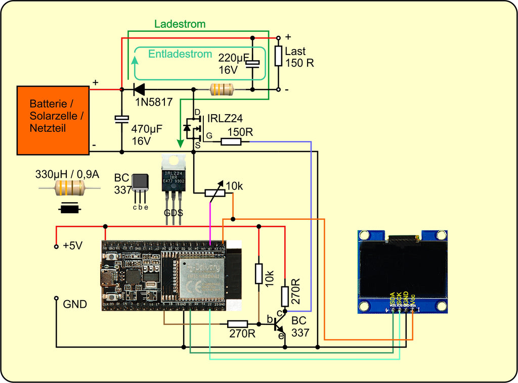
Image 5: Buck Converter - Circuit
The ESP32 is underpowered at the moment. It only operates the display and provides the PWM signal for the converter stage. But our project is expandable.
If you compare the circuit in Figure 5 with the one in Figure 4, you will surely notice that the switch, i.e. the MOSFET IRLZ24, is not in the plus line, but in the minus line. The positive line is the ground potential, so to speak. This is done so that the source terminal of the transistor is at the negative pole of the supply voltage, which is also connected to the GND level of the controller supply. If the MOSFET were placed in the positive line, then further circuitry would be required to equalize the levels. The operation of the circuit is identical to that described above, as you can see from the loops for the charge and discharge current.
The use of the BC337 requires another point to be considered. At collector c of the BC337, the signal of the ESP32 appears in inverted form because a logical 1 (3.3V) at the base b controls the transistor. At c is nearly GND potential, which corresponds to a logical 0. By the way, the pullup resistor at the base ensures a clean start of the circuit with disabled MOSFET. As long as the GPIO5 connector is still a high impedance input when the ESP32 is booted, the BC337 switches through and keeps the gate line of the MOSFET at GND potential.
An analog voltage of 0V to 3.3V is read in via the input VP = GPIO36. The value of the ADC converter (0 ...1023) is then taken to set the pulse width of the PWM signal. For details please refer to the discussion of the program.
The converter circuit is built on solder strips. It just as well that you could use a breadboard.

Image 6: Buck Converter - construction with contact strips
The display is controlled via the I2C bus. If it is supplied with 3.3V as shown in the schematic, there is no need for a level converter on the I2C bus lines SDA and SCL between the display and ESP32.
You should always remember the following:
- Between the positive pole of the output and GND there is always the full supply voltage of the battery, the solar panel, or the mains supply.
- The circuit cannot work if you connect GND to the negative pole at the output. This would also happen if the ESP32 was supplied from a USB port and the negative pole of the output was fed to further circuit parts whose GND potential is connected to that of the PC, i.e. via the protective conductor of the 230V mains. Specifically, this happens when the ground line (shielding) of the measuring cable is connected to the negative pole of the output with a DSO operated on the mains. Therefore, the acquisition of signals in the transducer range is only possible with a hand-held scope that has no connection to the protective conductor.
- The 5V supply of the ESP32 could also be derived from the supply voltage by means of a linear converter (LM7805).
In the table, I have summarized the needed parts.
Hardware
|
1 |
|
|
1 |
|
|
1 |
Potentiometer linear 10kΩ |
|
1 |
N-channel MOSFET IRLZ24 (Logic Level Gate, R on = 60mΩ) |
|
1 |
Transistor BC337 |
|
2 |
Resistor 270 Ω |
|
2 |
Resistor 150 Ω |
|
1 |
Resistance 10 kΩ |
|
1 |
Schottky diode 1N5817 |
|
1 |
Electrolytic capacitor 470µF 16V |
|
1 |
Electrolytic capacitor 220µF 16V |
|
1 |
Storage choke 330µH 1A |
|
various |
|
|
1 |
|
|
4 |
Soldering board with 6 contacts each or |
|
1 |
Base board 16cm x 24cm |
The software
For flashing and programming the ESP32:
Thonny or
Used firmware for the ESP8266/ESP32:
The MicroPython programs for the project:
ssd1306.py Hardware driver to the OLED display
oled.py API for the OLED display
converter.py Operating software of the converter
MicroPython - Language - Modules and programs
For the installation of Thonny you will find here a detailed manual (english version). In it there is also a description how the Micropython firmware (state 05.02.2022) on the ESP chip. burned is burned.
MicroPython is an interpreter language. The main difference to the Arduino IDE, where you always and only flash whole programs, is that you only have to flash the MicroPython firmware once at the beginning to the ESP32, so that the controller understands MicroPython instructions. You can use Thonny, µPyCraft, or, esptool.py to do this. For Thonny, I have described the process here described.
Once the firmware is flashed, you can casually talk to your controller one-on-one, test individual commands, and immediately see the response without having to compile and transfer an entire program first. In fact, that's what bothers me about the Arduino IDE. You simply save an enormous amount of time if you can do simple tests of the syntax and the hardware up to trying out and refining functions and whole program parts via the command line in advance before you knit a program out of it. For this purpose, I also like to create small test programs from time to time. As a kind of macro, they summarize recurring commands. From such program fragments sometimes whole applications are developed.
Autostart
If you want the program to start autonomously when the controller is switched on, copy the program text into a newly created blank file. Save this file as boot.py in the workspace and upload it to the ESP chip. The program will start automatically at the next reset or power-on.
Test programs
Manually, programs are started from the current editor window in the Thonny IDE via the F5 key. This is quicker than clicking on the Start button, or via the menu Run. Only the modules used in the program must be in the flash of the ESP32.
In between times Arduino IDE again?
If you want to use the controller together with the Arduino IDE again later, simply flash the program in the usual way. However, the ESP32/ESP8266 will then have forgotten that it ever spoke MicroPython. Conversely, any Espressif chip that contains a compiled program from the Arduino IDE or the AT firmware or LUA or ... can easily be flashed with the MicroPython firmware. The process is always like here described.
Signals on the I2C bus
How a transmission on the I2C bus works and what the signal sequence looks like, you can read in my article Mammoth Matrix Display - Part 2 read about it. I use an interesting little tool there, with which you can get the I2C bus signals to your PC and analyze them.
The program
For now, the program doesn't need to be able to do much. I let it sample the potentiometer at GPIO36 in the main loop, process the value, and output the result as a value for the duty cycle at pin GPIO5. This allows me to measure voltages from 0 to close to below the supply voltage at the output on the load. But first, let's go through the preparations.
# pwm power supply control
# converter.py
from machine import PWM,Pin,ADC,SoftI2C
from oled import OLED
from time import sleep
from sys import exit
I'm fine with the modules already integrated into the MicroPython kernel, but for the display, I need my oled module, which in turn relies on the ssd1306 module. The two files ssd1306.py and oled.py must therefore be uploaded to the flash memory of the ESP32. Please follow the two links for the download.
With the import of the corresponding modules and methods all defaults for the required objects are ready. By the formulation from xxxx import yyyy, zzzz I include the blueprints for the objects in the global namespace and save the referencing by the dot notation. However, I would overwrite already existing instances with the same name. But that is not the case here.
I now create the necessary instances for my application.
pwmPin=5
gate=PWM(Pin(pwmPin),freq=50000,duty=0)
The PWM signal is to be output at GPIO5. I set the frequency to 50kHz and the duty cycle to 0.
key=Pin(0,Pin.IN,Pin.PULL_UP)
For program control, I use the flash button of the ESP32. It is connected to GPIO0 and initialized as input with a pullup.
adcPin=36
Uout=ADC(Pin(adcPin), atten=ADC.ATTN_11DB)
Uout.width(ADC.WIDTH_10BIT)
I use GPIO36 =VP as analog input. I set the attenuator to ADC.ATTN_11DB and achieve the maximum voltage range of 0V ... 2,45V. But the converter always delivers the value 0 in the range of 0V to 0.15V. I set the resolution of the range to 10 bits. So the ADC delivers a maximum value of 1023, which corresponds to the voltage 2.45V, or better should correspond. An LSB would then have the value of 2.45 V / 1023 = 2.48 mV, theoretically. Because practically the converter curve is neither linear nor is there an offset of 0.
But attention:Never apply voltages higher than 3.6V to the inputs. Otherwise you can bury your controller on the graveyard of cuddly chips.
i2c=SoftI2C(Pin(22),Pin(21))
d=OLED(i2c)
d.clearAll()
To establish a connection to the display, the I2C bus must be activated. The SCL connection is at GPIO22, SDA is at GPIO21. The I2C instance i2c I pass to the constructor of the display object and then clear the display.
To make the voltage values less scattered, I let the ADC read the value more than once. For this, I made a function with the parameter count the number of measurements is passed as an argument.
The variable value is initialized with 0 and then I let in the for-loop count measurements to add up. The index n runs according to the MicroPython standard from 0 to count-1 and after the last run contains the contents of count which terminates the loop. The arithmetic mean of all measurements is returned as the function result.
def voltage(count):
    value=0
    for n in range(count):
        value=value+Uout.read()
    return value//count
With increasing voltage, the ADC delivers integer values between 0 and 1023. But because of the inversion of the PWM signal by the BC337, lower duty cycle values correspond to a higher voltage at the load. I take this into account when processing the PWM value by subtracting the ADC value from 1024. We enter the main loop.
while 1:
    value=1024-voltage(25)
    d.writeAt("{}     ".format(value),3,2)
    value=min(max(value,2),930)
    gate.duty(value)
    sleep(0.1)
    d.writeAt("{}     ".format(value),3,3)
    if key.value()==0:
        exit()
As a check, I display the contents of the value in the display and see everything from 0 to 1023 when I turn the potentiometer while the program is running.
But now it turns out that the duty cycle cannot be specified from 0 to 1023, as it says in the MicroPython description of the ESP32, but only from about 2 to 930. Therefore I limit the ADC value also to this range. I set the duty cycle with it and also let me see the corrected value in the display.
By pressing the flash key the running program can be terminated.
It will be exciting - the test
We want to see if everything works properly. As supply voltage, I connect a battery or an accumulator to the input. Parallel to the load I connect a DVM (Digital Volt Meter) and the collector of the BC337 I connect the input to a channel of the DOS (Digital Storage Oscilloscope). Then I start the program.
The voltmeter shows me voltages between 0.3mV and 4.88V when the potentiometer is on the left and right stop respectively. On the screen of the DSO, the square wave of the PWM signal appears.

Image 7: PWM signal
The corrected ADC value of 233 corresponds to a duty cycle of 69.3% and a voltage of 3.22V with a supply voltage of 4.98V.
ESP32 and current measurement - outlook
Could the ESP32 also measure the current through the load? Answer from Radio Yerevan: In principle yes, but only by using an operational amplifier to boost the voltage drop across a low impedance shunt and only at the cold end of the supply voltage before the source terminal of the MOSFET. But the problem is that the ESP32 cannot detect voltages up to 0.15V at all. And 0.15V at a resistor of 0.1Ω already corresponds to a current of 1.5A. Raising a voltage close to the GND rail requires special operational amplifiers that can work rail to rail.
But don't worry. In the next episode, I'll talk about finding the MPP (maximum power point) of solar panels. And there I use a true jack-of-all-trades that can measure voltage current and power more accurately than the ESP32 could ever dream of. Of course, our converter is used again, not as a controllable voltage source, but as a variable load resistor.
By the way, our step-down converter also gives a usable AC voltage source. Just replace the potentiometer turns with a function that periodically runs through values between 2 and 930, for example, sine or triangle or sawtooth or ...
Have fun researching! See you next time.
Here comes the program converter.py as a complete listing:
# pwm-power-supply-control
# converter.py
from machine import PWM,Pin,ADC,SoftI2C
from oled import OLED
from time import sleep
from sys import exit
pwmPin=5
gate=PWM(Pin(pwmPin),freq=50000,duty=0)
button=Pin(0,Pin.IN,Pin.PULL_UP)
adcPin=36
Uout=ADC(Pin(adcPin), atten=ADC.ATTN_11DB)
Uout.width(ADC.WIDTH_10BIT)
i2c=SoftI2C(Pin(22),Pin(21))
d=OLED(i2c)
d.clearAll()
def voltage(count):
value=0
for n in range(count):
value=value+Uout.read()
return value//count
i=0
while 1:
value=1024-voltage(25)
d.writeAt("{} ".format(value),3,2)
value=min(max(value,2),930)
gate.duty(value)
sleep(0.1)
d.writeAt("{} ".format(value),3,3)
if key.value()==0:
exit()


4 comments
Jürgen Grzesina
@edu
Die Dinger hatte ich auch auf dem Schirm, aber die waren mit für den gewünschten Bereich (bis 1 A) zu ungenau.
Jürgen Grzesina
@Hardy
Im Prinzip ja, aber
ein Optokoppler hat einen kleinen maximalen Kollektorstrom von 50mA, der BC337 kann 800mA. Höheres Schaltvermögen des Treibers kommt mit der Gatekapazität des MOSFET besser zurecht. Ein BC548 konnte das im Test auch nicht so gut.
Die Fotodiode schluckt bis zu 60mA bei 5V! Das kann der ESP32 gar nicht liefern
Ein Optokoppler kostst wenigstens das Sechsfache bis 40-fache des BC337.
Mit einem Optkoppler in der Plusschiene müsste auch ein P-Kanal-Mosfet verwendet werden. Die haben aber in der Regel einen größeren Ron.
Für eine geringe Verlustleitung am MOSFET barucht es einen möglichst kleinen Ron und steile Flanken. Der BC337 arbeitet bis 100MHz, Optokoppler liegen bei 500kHz.
Das waren bei der Auswahl der Teile die Punkte, über die ich nachgedacht habe.
Hardy
Hallo ein sehr interessantes Projek!
Frage könnte man statt dem BC337 nicht auch einfach einen Optokoppler verwenden?
VG Hardy
edu
potenialfreie strommesssensoren (5A; 20A; ..)gibt es v.d. Fa. ALLEGRO unter der der bez. ACS712 (f.5V Betr.Sp.) aber auch die ACS716 (f.3,3V Betr.Sp.) . dann kann a.d.ESP32 ein ADC die stromproportionale sensor-ausgangsspannung direkt wandeln und dann a.d.display ausgeben.