In the first part we had the installation of Thonny, the setup of the Raspberry Pi Pico, as well as the first application programs for using the inputs and outputs. This time, I would like to show you the programming of the familiar interfaces OneWire, UART and I2C, all of which are secondary pin assignments.
First of all once again the reference to the official Pinout diagram.

Also the MicroPython documentation, and especially the chapter RP2 I would like to cite again as a source.
Components used
Single wire bus (One Wire) at the example of the temperature sensor DS18B20
For the popular temperature sensor DS18B20, I myself prefer the waterproof variantThere are two modules that make programming very easy. First of all you need the OneWire library and then the library for the temperature sensor based on it. The circuit is very simple: The namesake "one" wire goes to pin 12 in my project. Please don't forget the pull-up resistor (4.7 kOhm) between signal wire and 3.3V. Like any electronic device, the sensor also needs a power supply, so the red wire to 3.3V and the black one to GND.
I try to connect several temperature sensors DS18B20 in parallel to one input.


With the above program, the three approximately equal temperatures are measured and output in the shell. Again, I copied the program fragments from the documentation and added them to an executable program. In the upper part onewire is imported and the object ow is instantiated. In the lower part of the program the module ds18x20 is imported first. After instantiating the object ds, the single-wire bus is scanned and the unique identifiers of the sensors are entered in the list roms list. The temperature values for all elements of the list are then determined and output in the for loop. This was easy, because the used modules are part of the program package. All these modules can be displayed. Have you already seen the reference to help() in the line before the prompt?

Here you will find the reference to help('modules') in the last line. Then all immediately available Python modules are displayed:

For the RP Pico there is another "built-in" module called rp2. After importing, you can also look at a little help for this:

More about this in the third part to this blog series. By the way, other microcontrollers also have specific modules with functions/methods, mostly extensions for the module machine.
For more information I refer to the official documentation.
DHT22
Next I would like to use a combined temperature/humidity sensor, which also needs only one pin except for the power supply: the DHT22.
Pinout of the DHT22:
- Pin 1 = VCC
- Pin 2 = Signal (to GP15 and via 10kOhm to VCC)
- Pin 4 = GND
There is no built-in module for this sensor, but hints for a module on the internet. Now we learn that the internal memory of the pico is quite useful after all. From now on the "other" modules will be stored there. But one step at a time.
On GitHub you can find a page for the DHT22 by Daniel Perron. Analyzing the program dht22test.py I notice that a program module named DHT22 is used, which can also be downloaded on the page. Without further ado I download the whole package as a zip file.
In addition, the test program contains code for displaying on an LCD. I want to show that later, so here is only my slim program for now dht22easyTest.py with display of temperature and humidity in Thonny. After I looked at the line with the instantiation of dht again and discovered the parameter Pin.PULL_UP, I wanted to know whether one can do without the external pull-up resistor. One can.

The picture of Thonny has changed a little bit. Under the menu item "View" I put a check mark by clicking on "Files" and so I bring up the directories on the PC (upper left) as well as on the RP Pico (lower left). There you will find DHT22.py and other modules we will use later. And by the way: If you save your program here under the name main.py (please don't use boot.py), you get an autostart function for the autonomous Pico.
LCD
Next I looked at the modules for the LCDs recommended by Daniel Perron. Their author's name is Dave Hylands, his GitHub - name is dhylands. Again I download the whole repository python_lcd as a zip file download.
From the multitude of files for different microcontrollers and the two connection options of the LCDs - GPIOs or I2C - I store the files lcd_api.py and machine_i2c_lcd.py in the internal memory of the Pico.
Addendum: The file lcd_api.py is needed for both versions. For the I2C version then use additionally machine_i2c_lcd.py. For the GPIO version please use the file nodemcu_gpio_lcd.py under the following link
https://github.com/dhylands/python_lcd/blob/master/lcd/nodemcu_gpio_lcd.py
and load it under the name gpio_lcd.py on the pico.
For a simple Real Time Clock (RTC) I first want to connect a LCD1602 to the GPIOs of the Pico.

The power supply of the LCD should rather be 5V, at 3.3V the picture is very weak.
Now please open my example program with the name Pico_GPIO-LCD1602_RTC.py
With the help of the module gpio_lcd the object lcd is instantiated with the pinout and display size in the program in the following line:
 lcd = GpioLcd(rs_pin=Pin(0),
               enable_pin=Pin(1),
               d4_pin=Pin(2),
               d5_pin=Pin(3),
               d6_pin=Pin(4),
               d7_pin=Pin(5),
               num_lines=2, num_columns=16)
Of course you can deviate from this pinout. If necessary, please note the deviating pin assignment in the original DHT22 test program by Daniel Perron, if you want to copy this.
After the values to be output have been assigned to a string for each line, the output is done with
lcd.putstr(line_up + "\n" + line_down)
To use the Real Time Clock, the class RTC from the module machine module. By uncommenting line 34, the date and time can be imported as a tuple with the values (year,month,day,weekday,hour,minute,second,microsecond). With rtc.datetime() without argument, date and time are queried and can then be evaluated via the index - starting at 0 as usual.
To my great surprise, the RTC in the powerless Pico continued to work overnight, so that after restarting the program the next morning the exact time was displayed. However, I cannot say how long the internal RTC continues to work without power supply.

Now the whole thing again from the beginning with my LCD2004 with I2C adapter. I have already saved the appropriate library, the module machin_i2c_lcd.py, on the pico. Please load the example program Pico_I2C-LCD2004_RTC.py
|
LCD with I2C adapter |
Raspberry Pi Pico GP |
Raspberry Pi Pico Pin |
|
GND |
GND |
3, 8, 13,18,23, 28, 33, 38 |
|
VCC |
VBUS = 5V |
40 |
|
SDA |
I2C0 SDA = GP8 |
11 |
|
SCL |
I2C0 SCL = GP9 |
12 |
With the lines
 from time import sleep
 from machine import I2C, Pin
 from machine_i2c_lcd import I2cLcd
 from machine import RTC
the necessary classes are imported from the modules.
The initialization of I2C and the LCD via I2C is done with
 i2c = I2C(0)                              # sda=pin(8), scl=pin(9)
 lcd = I2cLcd(i2c, 0x27, 4, 20)   # I2C address 0x27, 4 lines, 20 characters per line

In the sample program further functions/methods of the module are shown:
- lcd.move_to(column, line)
- lcd.backlight_off()
- lcd.backlight_on()
- lcd.display_off()
- lcd.display_on()
These are partially in the commented out part.
This is also the first time we have used one of the I2C interfaces, namely I2C(0) on pins GP8 and GP9.
Instead of another example for I2C I refer again to the Blog post by Jörn Weise from Nov.13.2021. In it he shows the temperature display on a 1.3" OLED with the I2C interface.
UART or also the serial interface, aka RS232
To test the serial interface, we need a remote station for communication. In previous blog posts, I had already presented a Python program using the Serial module on the Raspberry Pi. But here the focus should be on the Pico and MicroPython, so I use the Linux program minicom on the Raspi. Alternatively I could have used my PC with a USB-Serial-Adapter and the program Putty or the serial monitor in the Arduino IDE.
The connection between Raspberry Pi and RP Pico is quickly established. I first connect one ground pin at a time, then
TX = Pin(4) on the Pico to RX (phys. Pin 10) on the Raspi,
RX = Pin(5) on the Pico with TX (phys. Pin 08) on the Raspi.

Preparation at the Raspi:
 sudo apt update
 sudo apt install minicom
 sudo minicom -D /dev/ttyS0 -d 9600

To get a local echo in minicom, I press Ctrl+A and E in the terminal.

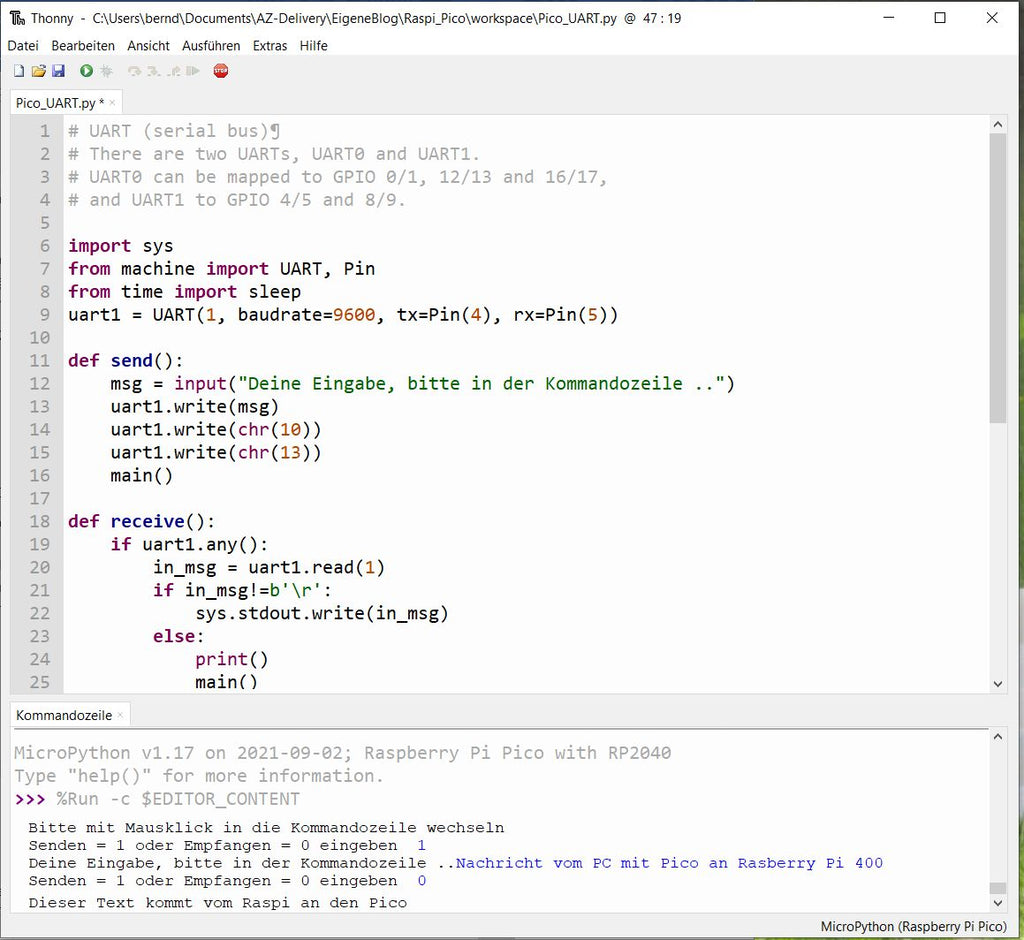
I have not found a suitable terminal program in MicroPython. Either there are examples for sending or receiving data. I would like to combine both. Maybe I didn't find the most elegant solution, but it works. Please load from the example programs now Pico_UART.py. Some explanations follow:
The module Serial module is not known to MicroPython. Instead there are in the module machine there is the class UART with few functions/methods. After importing the class we instantiate an object uart1 with the following command:
uart1 = UART(1, baud rate = 9600, tx = Pin(4), rx = Pin(5))
I declared the commands for sending and receiving data respectively in the self-defined functions send() and receive(), the switch between sending and receiving in the function main(). After many attempts, in which I could only terminate the program by pulling the USB plug, I added the command sys.exit() after the help of the blogger colleague Jürgen Grzesina. This terminates the program by pressing Ctrl+C. Before it jumped back into the infinite loop or waited for receive data.
Another little thing drove me to the edge of madness: After starting the program, the command line asks whether to send or receive. To send the "1" should be entered, to receive the "0", but it also works with any other character than "1". But the cursor does not jump automatically into the shell, but is still in the editor. So: first mouse click in the lower part of Thonny, the command line.
Here now the pictures of the exciting correspondence between Raspberry Pi 400 and RP Pico:

It is said: the appetite comes while eating. I hope I could infect you with my enthusiasm for the RP Pico and MicroPython and that you will try it out, too.


5 comments
Fabian
Hallo, danke für den tollen Einblick, habe Lust bekommen und werde mich im Winter an Ihrer Anleitung entlang arbeiten. Mfg
Guenter Purin
Hallo
vielleicht kann mir hier jemand weiter helfen
Pi Pico
Thonny editor
MicroPyhton
eigene Klasse: DRV8871_HBridge.py
auf dem Pico habebich einen Ordener erstellt mit dem Namen: myLib und inn diesem Ordern ist die Datei DRV8871_HBridge.py
main.py
from machine import Timer
import time
from myLib import DRV8871_HBridge
Motor1 = DRV8871_HBridge(7, 8, 1000)
c = 0
time.sleep(0.2) Motor1.SetPwmCcw© #Motor1.SetPwmCcwProcent(100) c = c+1 if c > 65535: c = 0while True:
leider funktioniert das Importieren nicht. Wenn die Klasse in Main.py ist, dann funktioniert alles super
Frage: was mache ich hier falsch?
Schon mal DANKE für die Hilfe
Schöne Grüße
Guenter
Jürgen
Warum behält die RTC des Raspi Pico die Uhrzeit?
Ganz einfach, weil er sich die Zeit bei jedem Neustart des Programms Pico_I2C-LCD2004_RTC.py die Zeit wohl automatisch vom PC her updatet. Das macht offenbar Thonny von sich aus, wenn das Programm von der IDE aus gestartet wird.
Wie stellt man das fest?
Wenn man das Programm als main.py auf dem Raspi abspeichert und danach die Verbindung zum PC abzwickt, um sie gleich danach wieder herzustellen (man kann auch kurz den Pin GP30 = RUN auf GND legen), dann startet das Programm mit der Anzeige: Freitag 1.1.2021; 0:00 (Epoche des Raspi). Das gleiche passiert, wenn man den Aufbau an einer externen Spannungsquelle anschließt, ohne USB. Durch den Reset wird eine etwaige Verbindung zum PC unterbrochen und Thonny kann keine Infos mehr mit dem Raspi austauschen.
Stellt man danach in Thonny durch Klick auf den STOP-Button die Verbindung zu REPL wieder her, und startet das Programm von dort, dann hat der Kleine wieder die Uhrzeit vom PC.
Im stromlosen Zustand kann keine RTC weiterlaufen, es ist ja schließlich kein Akku, Goldcap oder Ähnliches auf dem Pico.
Gruß Jürgen
Bernd Albrecht
Auf die github-Seite https://github.com/dhylands/python_lcd wurde bereits im Blog hingewiesen. Im Verzeichnis lcd findet man die benötigten Module. Die Datei lcd_api.py wird für beide Versionen gebraucht. Für die I2C-Version dann zusätzlich machine_i2c_lcd.py benutzen; und für die GPIO-Version bitte die Datei nodemcu_gpio_lcd.py unter folgendem Link
https://github.com/dhylands/python_lcd/blob/master/lcd/nodemcu_gpio_lcd.py
laden und unter dem Namen gpio_lcd.py auf dem Pico abspeichern.
Martin
Hallo,
ich habe für die Realtime Clock das ganze GitHub Verzeichnis in Thonny eingebunden, die beiden genannten Dateien auf dem Pico gespeichert und wenn ich das Script starte, heißt es immer:
ImportError: no module named ‘gpio_lcd’
In dem Verzeichnis gibt es nur eine Datei pyb_gpio_lcd.py, aber selbst wenn ich den import Befehl von:
from gpio_lcd import GpioLcd in:
from pyb_gpio_lcd import GpioLcd ändere, wird diese nicht gefunden.
Wo liegt mein Fehler?