My enthusiasm for the Raspberry Pi Pico W continues. Even with the model without WiFi, you could implement a lot of projects. Therefore here again is the link to the previous articles:
In the first part, we had the installation of Thonny, the establishment of the Raspberry Pi Pico as well as the first application programs to use the inputs and outputs. The second part dealt with the programming of the well-known interfaces OneWire, Uart, and I2C, all of them second assignments of the pins. And In the third part, we presented an application for the latest and fastest interface Spi or Serial Peripheral Interface AKA 4-Wire Bus. Already in autumn 2021, Jörn Weise had one Weather station with the Sensor BME280 and the 0.96-inch OLED SSD1306 display shown.
In my Contribution from January 3, 2023, I used the advantages of the WLAN interface and made temperature and relative humidity provided with the web server in the home network. In it, I had already announced that I would also like to implement a smartphone control for my Robot Cars fleet. Here we go
Used Hardware
|
1 |
Raspberry Pi Pico W or WH |
With the WH model, the pinbags are already soldered |
|
1 |
|
|
|
1 |
alternative | |
|
1 |
alternative | |
|
Div. |
||
|
1 |
Any smartphone with a browser app |
Preparation
For anyone who has not yet installed or updated the Thonny development environment, here again, the link:
Download of https://github.com/thonny/thonny/releases
Currently in January 2023: Thonny-4.0.1.exe
As sources for the post, I primarily use the publications of the Raspberry Pi Foundation:
Raspberry Pi Pico W Datasheet and
Connecting to the Internet with Raspberry Pi Pico W
as well as the book of Paul Fuchs "HTML5 and CSS3 for beginners", with which I succeeded in starting with the HTML award language.
Now finally to smart car control. In the past two years, I have always used driving stages and a simple code for radio transmission. The driving levels have proven themselves because the code should not be complex and tensions below 50% of the nominal voltage of the engines only lead to the engine buzzing but does not rotate. I currently use a four-digit code in which the first two places are used for the journey including cornering and the third and fourth place for additional functions that can be triggered by buttons.
Examples of the control code
Code 9500 for the fastest straight-ahead, 5500 for standstill, 7700 for a forward trip to the right, and values below 5 stand for a reverse ride (1st place) or left-wing curves (2nd position)
|
Y <0 x → |
1 |
2 |
3 |
4 |
5 |
6 |
7 |
8 |
9 |
|
9 |
← |
↖ |
↑ |
↗ |
→ |
||||
|
8 |
← |
↖ |
↑ |
↗ |
→ |
||||
|
7 |
← |
↖ |
↑ |
↗ |
→ |
||||
|
6 |
← |
↖ |
↑ |
↗ |
→ |
||||
|
5 |
← |
↖ |
0 |
↗ |
→ |
||||
|
4 |
← |
↙ |
↓ |
↘ |
→ |
||||
|
3 |
← |
↙ |
↓ |
↘ |
→ |
||||
|
2 |
← |
↙ |
↓ |
↘ |
→ |
||||
|
1 |
← |
↙ |
↓ |
↘ |
→ |
With the third and fourth place, as I said, you can activate additional functions that can be triggered by up to 7 buttons. Depending on the button, the value of the two potencies is added. Attention: counting the button begins at zero.
|
Button |
0 |
1 |
2 |
3 |
4 |
5 |
6 |
|
Value |
1 |
2 |
4 |
8 |
16 |
32 |
64 |
Example
In this project I only use two buttons/buttons, i.e. the third place of the code is not required. Fourth value = 0 does not mean buttons, value = 1 means button 0 (here button for blue light) pressed, and value = 3 means button 0 and 1 (blue light and siren) pressed.
This four-digit code can be used with the Joystick Shield or Joystick module as well as with a Keypad module (e.g. the LCD Keypad Shield) to be used. In the first case, the values of the joystick potismap-Ped ”, in the second case, the values for the driving levels are increased or reduced when the driving levels are pressed. Based on the Keypad, I will program buttons in the browser to enter the journey commands via WLAN.
cabling
Microcontroller, the Raspberry Pi Pico W is no exception, delivers to the pins "signals", but hardly enough electricity for real consumers like our engines. That is why we need so-called motor drivers with ICs such as the L293 or L298. For several reasons, I have the small circuit board Smart Car Kit with the Motor Controller L298N decided. First, I only use two engines, so why pay for four engines? Second, the IC is provided with a heat sink and thirdly the board can deliver the voltage for the Pico W.
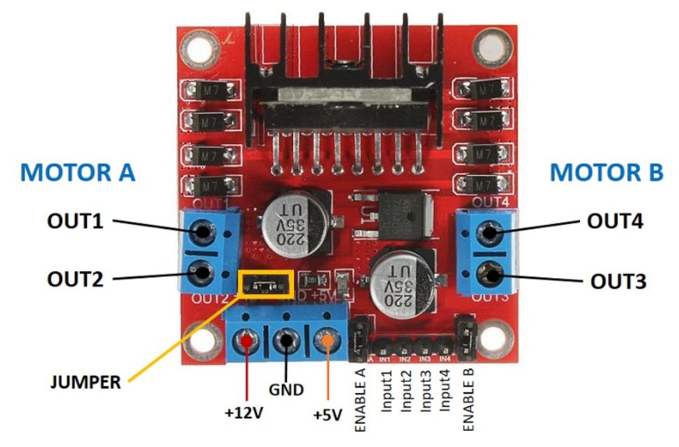
So that we can connect the microcontroller to +5V and GND, the jumper must be stuck. On the other hand, the short circuit bridges are removed to Enable A and Enable B. All six tax lines are connected to the PICO W starting pin. The enable pins are defined as PWM pins in order to regulate the speed of the engines.
The cables for inputs 1 to 4 are connected to normal pins and are attached with high or low to determine the direction of rotation. The enable pins are declared as PWM. If an engine turns incorrectly, you can either polish the engine or replace the pin number in the code.
Source code
 From machine import Pin code, PWM
 …
 m1e = PWM(Pin code(11))
 m11 = Pin code(13,Pin code.OUT)
 m12 = Pin code(12,Pin code.OUT)
 m2e = PWM(Pin code(20))
 m21 = Pin code(19,Pin code.OUT)
 m22 = Pin code(18,Pin code.OUT)
I took over the engine (C1, C2) from previous programs. The parameters C1 and C2 are the first two places of the code.
I had to adjust the value for
factor = 65535 * 6/vbatt # Max PwM * 6 / VBatt
Because the method duty_u16 A 16-bit value expected for the PWM and the supply voltage must be regulated to the permissible 6V of the motor.
The (for me) difficult part lies with the HTML code in order not only to transfer data to WLAN but also to transmit control signals to the Smart Car.
With the lines
HTML = "" ""
Smart Car Control Panel
"""I create the required buttons for control in the browser (either PC or smartphone). The current code is displayed as feedback at the bottom. Here is a screenshot from my smartphone:
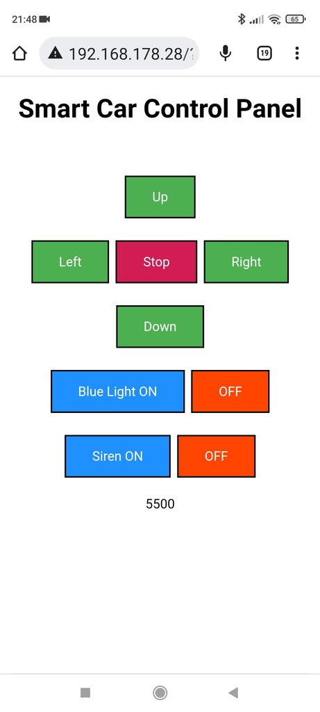
What happens when a button is clicked? The respective tax command will be with a slash/question mark. attached to the IP address of the smart car. Since HTML is only an award language but is not a programming language, the evaluation is carried out in the (Micro) Python program.
Examples:
Here is the program code as a whole (Download). I have not yet realized the blinking of the blue LED and the siren.
# HTTP Server Example
# Control a Robot Car and Blue Light/Siren Using A Web Browser
import time
import network
import socket
From machine import Pin code, PWM
# Define 4 Digits of Code
C1 = 5
C2 = 5
C3 = 0
C4 = 0
# Initialization of Blue LED
Led_blue = Pin code(14, Pin code.OUT)
# Initialization of Motors
vbatt = 9
m1e = PWM(Pin code(11))
m11 = Pin code(13,Pin code.OUT)
m12 = Pin code(12,Pin code.OUT)
m2e = PWM(Pin code(20))
m21 = Pin code(19,Pin code.OUT)
m22 = Pin code(18,Pin code.OUT)
m1e.freq(1000)
m2e.freq(1000)
factor = 65535 * 6/vbatt # Max PwM * 6 / VBatt
def engine(C1, C2):
y = C1 - 5 # Forward/Backward
X = C2 - 5 # Left/Right
Leftwheel = y + 0.5 * X
Rightwheel = y - 0.5 * X
IF Leftwheel > 4:
Leftwheel = 4
IF Leftwheel < -4:
Leftwheel = -4
IF Rightwheel > 4:
Rightwheel = 4
IF Rightwheel < -4:
Rightwheel = -4
IF Leftwheel < 0:
m11.off()
m12.on()
elif Leftwheel > 0:
m11.on()
m12.off()
Else:
m11.off()
m12.off()
# M1e.duty_u16 (0)
IF Rightwheel < 0:
m21.off()
m22.on()
elif Rightwheel > 0:
m21.on()
m22.off()
Else:
m21.off()
m22.off()
# M2e.duty_u16 (0)
LeftPWM = intimately(factor * (0.2 + 0.2*Section(Leftwheel)))
print("LeftPwm =", LeftPWM)
Rightpwm = intimately(factor * (0.2 + 0.2*Section(Rightwheel)))
print("Rightpwm =", Rightpwm)
m1e.duty_u16(LeftPWM)
m2e.duty_u16(Rightpwm)
SSID = '……' # your wifi ssid
password = '……’ # your wifi password
wireless Internet access = network.WIRELESS INTERNET ACCESS(network.Sta_if)
wireless Internet access.active(True)
wireless Internet access.connect(SSID, password)
HTML = "" ""
Smart Car Control Panel
"""
# Wait for connect or fail
max_wait = 10
while max_wait > 0:
if wlan.status() < 0 or wlan.status() >= 3:
break
max_wait -= 1
print('waiting for connection...')
time.sleep(1)
# Handle connection error
if wlan.status() != 3:
raise RuntimeError('network connection failed')
else:
print('Connected')
status = wlan.ifconfig()
print( 'ip = ' + status[0] )
# Open socket
addr = socket.getaddrinfo('0.0.0.0', 80)[0][-1]
s = socket.socket()
s.bind(addr)
s.listen(1)
print('listening on', addr)
# Listen for connections, serve client
while True:
try:
cl, addr = s.accept()
print('client connected from', addr)
request = cl.recv(1024)
print("request:")
# print(request)
request = str(request)
StopButton = request.find('Stop=0')
if StopButton==8:
print( 'StopButton is pressed')
c1 = c2 = 5
UpButton = request.find('Up=1')
if UpButton==8:
print( 'UpButton is pressed')
if c1 < 9: c1 +=1
LeftButton = request.find('Left=2')
if LeftButton==8:
print( 'LeftButton is pressed')
if c2 > 1: c2 -=1
RightButton = request.find('Right=4')
if RightButton==8:
print( 'RightButton is pressed')
if c2 < 9: c2 +=1
DownButton = request.find('Down=3')
if DownButton==8:
print( 'DownButton is pressed')
if c1 > 1: c1 -=1
BlueLightON = request.find('BlueLightON=5')
if BlueLightON==8:
print( 'Blue Light ON is pressed')
c4 = 1
BlueLightOFF = request.find('OFF=6')
if BlueLightOFF==8:
print( 'Blue Light OFF is pressed')
c4 =0
SirenON = request.find('SirenON=7')
if SirenON==8:
print( 'SirenON is pressed')
c4 = 3
SirenOFF = request.find('OFF=8')
if SirenOFF==8:
print( 'SirenOFF is pressed')
c4 = 1
if c4==1 or c4==3:
led_blue.on()
else:
led_blue.off()
code = 1000*c1 + 100*c2 + 10*c3 + c4
print("Code = ",code)
Code = str(code)
response = html + Code
cl.send('HTTP/1.0 200 OK\r\nContent-type: text/html\r\n\r\n')
cl.send(response)
cl.close()
motor(c1,c2)
except OSError as e:
cl.close()
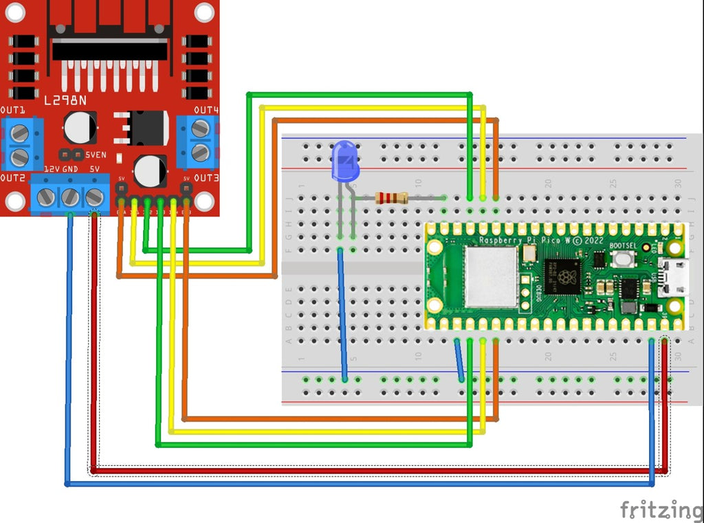
print('connection closed')Here is a picture of my experimental setup. I decided to use a breadboard with female headers for the Pico W. The motor controller L298N is located below the board. The red cable (bottom right in the picture) comes from the 5V connector of the L298N and is connected to VSYS when driving.

The program code is certainly not perfect yet but shows the active possibilities with HTML. The blue LED does not blink yet, because this should, of course, be done "non-blocking", i.e. without time.sleep(1), and the method Timer() from the module machine caused the LED to blink faster with every call so that the pico did nothing else at the end. The function/method Timer.deinit() did not lead to the end of flashing. I was not able to clarify whether this is a bug or my mistake.
Nevertheless, you can use the code for the LED, for example, to switch a relay for the coffee machine. So also home automation / IoT applications are possible.
During the development, I started the µpython program on the PC and finally saved it on the Pico under the name Main.py for the autostart. In the event of changes, I stopped the program and made the changes. When starting again, I occasionally received the following error message in the command line (Shell):
Traceback (Most Recent Call Last):
File "" , Line 133, in
Oserror: [Errno 98] Eaddrinuse
Then only helps to pull the USB connector and re-connect the Pico. Because the button on the pico is not a reset button but is called the boat and is only pressed if you want to install µpython, for example.
Critical evaluation of the driving characteristics of my robot car
In our living room, there are too many obstacles to control the smart car with your smartphone without an accident. It works in principle, but my radio remote control with Joystick Shield and 433 MHz transceiver HC-12 works better. As mentioned above, you can easily modify the HTML part of the program and use the buttons on the smartphone for switching LEDs or relays.


6 comments
Andreas Wolter
@Henry: im Abschnitt “Verwendete Hardware” sind die Komponenten aufgeführt, die für dieses Projekt verwendet wurden. Das Robot Car wird vom Raspi Pico gesteuert.
Die Basics der jeweiligen Programmiersprache sind sehr wichtig. Allerdings sinkt die Konzentration rapide, wenn man alles nur theoretisch macht. Python ist etwas einsteigerfreundlicher, da man sich nicht vorrangig um Typisierung kümmern muss. Es ist wichtig zu wissen, wann Kontrollstrukturen zum Einsatz kommen und wie man sie verwendet. Python und MicroPython unterscheiden sich dann auch. Zweites wird für die Mikrocontroller verwendet. Also muss man sich dann auch um Ein- und Ausgangspins kümmern. Etwas Elektrotechnik ist ebenfalls wichtig, da zum Beispiel in einigen Fällen 5V Spannung anliegt und in anderen Fällen wie beim ESP dann nur 3,3V.
Ich würde zuerst das Ziel vorstellen, dann wie man die Entwicklungsumgebung verwendet, dann einen Grundkurs in Python geben und dann dieses Projekt hier zum Laufen bringen. Anschließend den Code veränden, damit man sieht, wie er funktioniert. Ich denke, dass man das so ab 7. oder 8. Klasse machen könnte. Zeit ist natürlich ein wichtiger Faktor. Zu Hause kann man da schonmal 8 Stunden dran sitzen. Das geht in der Schule nicht.
Grüße,
Andreas Wolter
AZ-Delivery Blog
Henry
Sehr interessantes Projekt, ich würde daraus gerne ein Projekt mit Schülern machen, um die Programmierung mit Python zu vermitteln.
Haben Sie bei den Robot car Bausatz den Arduino und die dazu gehörige HAT völlig durch den Raspi pico ersetzt? Oder ist der Arduino weiter im Einsatz (Kann ich hier nicht erkennen, aber trotzdem sicherheitshalber die Nachfrage) ?
Hat jemand Erfahrungen für ein solches Projekt mit Schülern (bei welcher Klassenstufe sinnvoll, evt sogar Vorgehensweise in einzelnen Schritten)?
Viele Grüße von Henry
Andreas Wolter
@Michael: können Sie andere Beispiele aus den vorangegangenen Beiträgen auf dem Pi ausführen?
Sie könnten in Thonny über REPL die Befehle manuell eingeben. Zum Beispiel die imports der Bibliotheken. Dann müssten Sie sehen, ob eine Fehlermeldung erscheint. Der Server wird wahrscheinlich über die “network”-Bibliothek implementiert. Damit würde ich es zuerst versuchen.
Grüße,
Andreas Wolter
AZ-Delivery Blog
Michael
Ich bekomme den HTTP Server nicht zum laufen muss ich das Programm in Bibliotheken aufteilen oder noch was anderes auf den Pico WH speichern . MFG Michael
Andreas Wolter
Ferdinand Weiß: um von außen den Roboter zu steuern, müssten Sie eine externe Verbindung schaffen, damit der Mikrocontroller erreichbar ist. Die IP des MC ist lokal. Sie müssten in Ihrem Internetrouter eine Weiterleitung einrichten.
Es gibt Kameras für den Pico.
Ich habe spontan das hier gefunden: https://www.youtube.com/watch?v=qLee7ThjOp4
Die Bildrate ist erwartungsgemäß gering. Aber eventuell könnte man die Sketches kombinieren.
Grüße,
Andreas Wolter
AZ-Delivery Blog
Ferdinand Weiß
Hallo,
cooles Projekt!
Aber kann man das Auto auch von einem anderen Netzwerk oder mobilen Daten steuern? Oder was müsste man dann ändern?
Wäre es auch möglich, gleichzeitig einen Videostream einer Kamera in die Website einzubauen, um die Umgebung zu sehen?
Grüße aus Niederbayern
Ferdi