This post is also as PDF document available.
While there are a whole range of sensors available to record temperature, humidity, air pressure, illuminance... we have to dig into the toolbox to build a sensor for precipitation. It is simply a matter of recording relatively small amounts of liquids, which do not represent a continuous flow but, in the truest sense of the word, appear in droplets. These droplets need to be collected. When the potty is filled with droplets, it must be emptied automatically and this process must be registered. I copied the principle from commercial devices on the Internet. A rocker with two bowls is mounted so that it can be easily rotated and tilts when a certain filling level is reached. This tipping process must now be recorded by suitable sensors. You'll find out how it went in detail, including wrong turns, in the next episodes of the series
MicroPython on the ESP32 and ESP8266
today [1]
The ESP32 as a rain gauge – Part 1
In today's episode we'll take care of the mechanics of the project, look at how reed contacts work and create an initial small test program that we'll expand on in the next two episodes. To do this, we use MicroPython’s bag of tricks. You will learn about interrupts, contact bounce and how to turn it off programmatically. Finally, we will transfer the files with the measured values to the PC via FTP, using threading technology.
mechanics
The seesaw
The sensor for measuring the amount of rain is a rocker with two trays.

Figure 1: Base part of the apparatus
Here the rocker is already installed in the bottom part of the measuring tube. I used a cover from a 100 gauge PVC sewer pipe. Two openings were sawn so that the water can drain away.

Figure 2: Rain seesaw pattern
Figure 2 shows the pattern of the rocker, which was made from 2mm Plexiglas. The 1:1 template in the form of a PDF file, can be downloaded. I used PLEXIGLAS® adhesive “Acrifix 192” for gluing. It fills gaps and hardens under UV light or simply daylight. I glued the template parts to the acrylic glass with a water-soluble glue stick. After sawing and drilling, you can simply remove the paper again. Don't forget to clean areas to be glued with acetone or isopropanol.
The position of the 1.5mm hole for the shaft made of 1.4mm copper wire (the shaft should not rust, so do not use iron) determines how easily the rocker tilts. This increases the higher the hole is above ground. I use the top hole and get a capacity of approx. 2.4 cm³ until the rocker tips over. We'll take a look later at what amount of rain this amounts to based on the area.
What can you do wrong? The resolution of the volume measurement is better if the rocker is as light as possible. So you should use the thinnest possible material and as little glue as possible. My first attempt at making the rocker out of tinplate or copper sheet was a total flop. The volume of the tubs was not sufficient to cause the seesaw to tip over because the construction was far too heavy.
The suspension of the rocker is also made of acrylic glass. The side panels are screwed to the 6 mm thick base plate so that the thing can be taken apart. The dimensions can be found in Figure 3.

Figure 3: Rocker bracket
To prevent the rocker from rubbing against the side walls, I placed small plexiglass discs between them.

Figure 4: Rocker from the side

Figure 5: Seesaw, view from north-east
In order for the precipitation to land specifically in the trays, it must be collected over an area of known size and guided via a funnel to just above the seesaw. Of course, only one of the two halves may be filled at a time. There are three things to consider.
● The tubs have to be wide enough so that nothing goes wrong.
● The top edge of the partition must be far enough from the fall line of the water drops.
● And, because large funnels usually have thicker outlet tubes, I had to use the nozzle of a silicone cartridge to create a thinner outlet. The nozzle was simply glued into the funnel with silicone.
A 100 mm sewage pipe that supports the funnel was cut to length so that the funnel can be placed in the correct position. Figure 5 shows the three components of the mechanics.

Figure 6: The mechanical parts of the rain gauge
This is what the finished device looks like. The opening in the tube allows control when aligning the funnel precisely. If necessary, the sawn out piece can be fitted with hinges and used as a door.

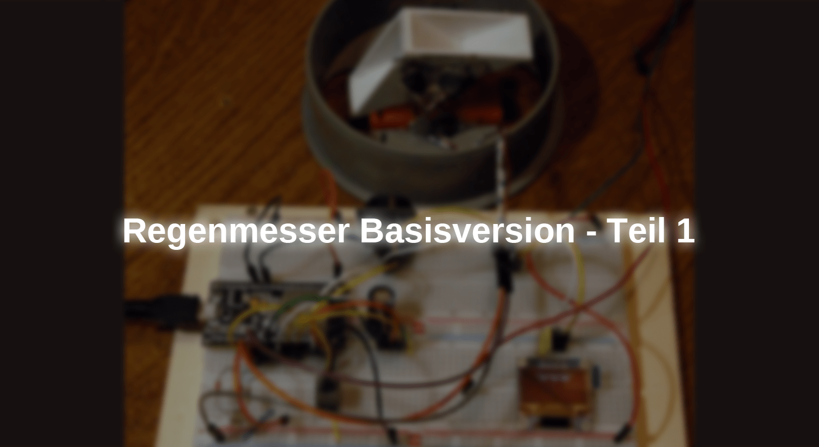
Figure 7: Measuring station assembled
Register tilting movement
Let's get to the determination of the tilting movement. Measurements with a pipette have shown that the rocker tilts to the right and left with slightly different filling quantities, 2.4cm³ and 2.5cm³. This circumstance apparently resulted from uneven adhesive application or other asymmetries. So both stable end positions had to be detectable. Initially I planned to use an MPU6050 accelerometer in the form of a GY 521 module. However, the four cables required interfered so much with the tilting of the rocker that I had to refrain from doing so. Reflective light barriers were too bulky for me and so I ended up using reed contacts.
These are small, magnetically operated switches in a glass tube measuring 2mm x 13mm. The common thing about these things is the rigid connecting wires. I killed four of the contacts, because if you bend it too close to the glass, it will immediately shatter and kill the component.

Figure 8: Reed contact
Finally we managed to attach two of the things to one side wall of the holder using two-component putty. Looks wild, but works well. It is best to attach the lead in the same way.

Figure 9: Location of contacts and magnet
A small neodymium disc magnet is glued to the rocker (Acrifix) and the contacts are aligned according to this position. Figure 10 illustrates how the reed contacts work and explains why this type of magnet must not be located exactly in front of the contact.

Figure 10: How a reed contact works
The contact is open outside of magnetic fields (1). The contact springs are made of a ferromagnetic material, probably iron or a corresponding alloy. The poles of a disc magnet sit on the cut surfaces. If you approach the reed contact, the iron wire (bottom) becomes a magnet (south pole) due to magnetic influence and attracts the second contact spring. The contact closes (2).
If you were to slide the disk magnet centrally under the contact, similar poles would be influenced in the springs. Because they repel each other, the contact cannot close (3).
Small bar magnets can be placed directly parallel to the contact. Because different poles in the contact springs are then influenced, the contact closes (4).
Hardware
For both controller families, ESP32 and ESP8266, you first have to think about the GPIO pins that can be used. Some of them are integrated into the boot process and therefore cannot be used without restrictions. In addition to three IRQ inputs, a button input and an LED output, we also need the I2C and SPI buses, which alone occupy 6 pins. The tables provide information about the use of the pins. With the ESP8266, in addition to the bus lines, only 3 GPIO pins remain, of which D0 = GPIO16 is not IRQ-capable. The “little ones” are therefore excluded from our project.
But there is also a problem with the ESP32. Pin 12 must not be HIGH when booting, otherwise the controller will not boot up. Unfortunately, this connection is the MISO line of the SPI1 bus and is pulled to 3.3V by the slave. Therefore SPI1 is taboo. So use SPI2 or Soft-SPI. We'll get to that in the next post.


Let's move on to the parts needed for the project. The table lists all the components that are needed throughout the entire project. In this first episode, the ones highlighted in gray are not used at first.
|
1 |
ESP32 Dev Kit C V4 unsoldered or ESP32 NodeMCU Module WLAN WiFi Development Board with CP2102 or |
|
1 |
|
|
1 |
|
|
1 |
SPI Reader Micro Memory SD TF Card Memory Card Shield Module |
|
1 |
SD card for example 8GB |
|
1 |
|
|
1 |
|
|
1 |
|
|
1 |
LED |
|
1 |
Resistance 220Ω |
|
2 |
Resistance 10kΩ |
|
1 |
Micro switch button set - 180 pieces, various sizes, versatile buttons for electronics |
|
optional |
Table 3: Components
Of the 10 reed contacts in the set, 2 are needed (or like me, six).
The circuit diagram in Figure 11 shows how the parts are connected.

Figure 11: Rain gauge circuit
The software
For flashing and programming the ESP32:
Thonny or
Firmware used for an ESP32:
The MicroPython programs for the project:
timeout.py Non-blocking software timer
oled.py OLED API
ssd1306.py OLED driver
rain knife.py Demo program
MicroPython - language - modules and programs
To install Thonny you can find one here detailed instructions (english version). There is also a description of how to do this Micropython firmware (as of June 18, 2022) on the ESP chip burned becomes.
MicroPython is an interpreter language. The main difference to the Arduino IDE, where you always and exclusively flash entire programs, is that you only need to flash the MicroPython firmware once at the beginning on the ESP32 so that the controller understands MicroPython instructions. You can use Thonny, µPyCraft or esptool.py to do this. I have the process for Thonny here described.
Once the firmware is flashed, you can have a casual conversation with your controller, test individual commands, and immediately see the response without having to compile and transfer an entire program first. That's exactly what bothers me about the Arduino IDE. You save a lot of time if you can carry out simple syntax and hardware tests through to trying out and refining functions and entire program parts via the command line before you build a program out of it. For this purpose, I always like to create small test programs. As a kind of macro, they combine recurring commands. Entire applications sometimes develop from such program fragments.
Autostart
If you want the program to start autonomously when the controller is switched on, copy the program text into a newly created blank file. Save this file as main.py in the workspace and upload it to the ESP chip. The next time you reset or switch on, the program starts automatically.
Test programs
Programs are started manually from the current editor window in the Thonny IDE using the F5 key. This is faster than clicking on the start button or using the menu run. Only the modules used in the program must be in the flash of the ESP32.
Arduino IDE again in between?
If you later want to use the controller together with the Arduino IDE again, simply flash the program in the usual way. However, the ESP32/ESP8266 then forgot that it ever spoke MicroPython. Conversely, any Espressif chip that contains a compiled program from the Arduino IDE or the AT firmware or LUA or ... can easily be provided with the MicroPython firmware. The process is always like this here described.
A first test
It's best to start with this Upload the following files to the ESP32 flash:
oled.py, ssd1306.py, ds3231.py and timeout.py
When everything is assembled, we start the first tests. In REPL let's enter the following lines. The beauty of MicroPython is that you can test the effect of commands from the command line before incorporating them into a program. That's exactly what we're doing now. We put the rocker in the left position. The entries are formatted in bold, the system answers in italics.
>>> from machine import Pin
>>> reedR = Pin(16,Pin.IN)
>>> reedL = Pin(17,Pin.IN)
>>> reedR()
1
>>> reedL()
0
After folding the rocker:
>>> reedR()
0
>>> reedL()
1
So that works. When querying the levels, I use the property of pin objects callable, i.e. to be callable. This is done by the method Pin.__call__() enables. She belongs to the so-called Magic methods and allows the object to be called like a function. The following instructions should therefore be used synonymously.
>>> reedR(1)
>>> reedR.value(1)
>>> reedR.on()
Or
>>> reedR()
0
>>> reedR.value()
0
>>> reedR.on()
0
Next test: I2C bus. We bind the module SoftI2C one, instantiate an object, i2c and look at who is represented on the bus.
>>> from machine import Pin, SoftI2C
>>> i2c=SoftI2C(scl=Pin(22),sda=Pin(21),freq=100000)
>>> i2c.scan()
[60, 87, 104]
You're probably surprised that three peripheral device addresses are found, since we only have two modules on the bus. Yes, but - in addition to the RTC chip, the DS3231 module also has a 32Kb = 8KB EEPROM with the hardware address 87 = 0x57 on the board. Of interest to us are the 60 = 0x3C (OLED) and the 104 = 0x68 (DS3231). The EEPROM could be used, for example, to permanently store configuration data. So it works too.
Oled display: When instantiating, we pass the I2C object and tell the API that our display is 64 pixels high.
>>> d=OLED(i2c,heightw=64)
this is the constructor of OLED class
Size:128x64
>>> d.writeAt("Hello World",3,0)
13
"Hello world" is printed in the middle of the top line. The returned value 13 is the next free writing position in the line.
The RTC (Real Time Clock) is also on the I2C bus. We therefore also pass the I2C instance to the constructor of the RTC object. Then we set the date and time and get the time. A tuple with the following seven values is to be passed (year, month, day, day of the week, hour, minute, second). It is also worth the very extensive module ds3231.py to take a closer look.
>>> rtc=DS3231(i2c)
DS3231 ready @ 0x4C
>>> rtc.DateTime((2024,6,14,5,14,19,30))
>>> rtc.Time()
[14, 19, 32]
The ESP32 also has an RTC, but it does not have an alarm timer. In order to get an alarm clock function, we have to use the DS3231 and – program interruptions, in short IRQs. They are used to report an external event to the running program and to request its operation by immediately interrupting the program (interrupt request).
The rocker contacts and the RTC can trigger such events by changing the level on a GPIO pin (pin change IRQ). We need to define a GPIO input for each event. The IRQ can be armed after an interrupt service routine (ISR) has been defined. In the parameter pin The triggering pin object is passed on by the system. The inputs are connected to external pull-ups of 10kOhm because the internal ones are too high impedance. This improves the slope – that’s what the DSO (Digital Storage Oscilloscope) told me.
>>> reedR = Pin(16,Pin.IN)
>>> reedL = Pin(17,Pin.IN)
led=Pin(2,Pin.OUT,value=0)
>>> def pinIRQ(pin):
global source
if pin==reedL:
source="L"
led(0)
elif pin==reedR:
source="R"
led(1)
>>> reedR.irq(handler=pinIRQ, trigger=Pin.IRQ_FALLING)
>>> reedL.irq(handler=pinIRQ, trigger=Pin.IRQ_FALLING)
When arming, the reference to the ISR is transferred and the falling edge is set as the trigger.
If the rocker is now tilted by hand, the LED lights up when tilted to the right and goes out when tilted to the left. – Spooky, right? – No program is running and the contacts are not directly connected to the LED circuit. The IRQs are therefore active even if no main program is running. What is now interrupted is REPL, the Read Eval Print Loops. And so we turn the magic off again.
>>> reedL.irq(handler=None)
>>> reedR.irq(handler=None)
We will use this to clean up when we leave the program and leave a clean room. We can trigger this process by pressing the button on GPIO4 - later, not now.
For the Heart beat (sign of life) during the running of the main loop we use the LED and a non-blocking software timer. This runs in the background without blocking the loop execution. The magic is all in one here Closure. This is a function encapsulated in a surrounding function definition. Because the inner function uses variables from the surrounding function, both the inner function and the variables remain alive after leaving the surrounding function. Normally, all of the innards of a function are mashed when they leave it. Oh mystical MicroPython – Ommm!
The surrounding function is called here TimeOutMs(). She lives in the module timeout.py, from where we import them. In TimeOutMs() lives the function compare(), which grabs the passed argument 5000 and also the current status of the timer tick. As long as the difference between other time stamps and the timer tick recorded at the beginning does not exceed 5000, the function delivers compare() returns the value False, otherwise True. TimeOutMs() returns a reference to when exiting compare() back and thus makes the closure immortal. We assign this reference to the identifier now flashing to and can use the function compare() under the pseudonym now flashing call at any time.
>>> from timeout import TimeOutMs
>>> nowBlinking=TimeOutMs(5000)
>>> nowBlink()
False
>>> nowBlink()
False
>>> nowBlink()
True
After five seconds, we get the result True. The function definition is quite puny, but worth investigating. To do this, simply open the file timeout.py in an editor window.
The program
With these hand tests we have basically already discussed the entire program. All elements appear again in perhaps a slightly different order, with a few small additions that are commented on.
# regenmesser.py
from oled import OLED
from machine import Pin, SoftI2C
from time import sleep_us, sleep, sleep_ms
from ds3231 import DS3231
import sys
from time-out import TimeOutUs, TimeOutMs
# externe 10k-Pullups bringen steilere Flanken!
reedR = Pin(16,Pin.IN) # rechts prellt 75us
reedL = Pin(17,Pin.IN) # links kein Prellen
key=Pin(4,Pin.IN,Pin.PULL_UP) # Tasteneingang an GPIO4
# mit internem Pullupwiderstand
led=pin(2,Pin.OUT,value=0)
i2cNamen={ # Das Dictionary erleichtert die Identifikation
0x57: "DS3231.EEPROM 32Kb",
0x68: "DS3231.RTC",
0x3C: "OLED",
0x40: "SHT21",
}
print("I2C-Devices @ ")
for i in i2cDevices: # Nummer in Hexcode und Klartext wandeln
print(hex(i),i2cNamen[i])
print()
d=OLED(i2c,heightw=64)
rtc=DS3231(i2c)
source="*"
# Inhalt der Kippschalen in ccm
cLinks = 2.4 # ccm
cRechts = 2.5
# Trichter Durchmesser d=10,9cm
area=(10.9/2)**2 * 3.1415 # Trichterfläche
bucketHour=0 # Der Sammeleimer
# IRQ service routine
def pinIRQ(pin):
global source # Damit der neue Wert die ISR verlassen kann
if pin==reedL:
source="L"
elif pin==reedR:
source="R"
def shutdown(): # Funktion zum Aufraeumen beim Beenden
reedL.irq(handler=None)
reedR.irq(handler=None)
print("von User abgebrochen")
# Pin Change IRQ scharfschalten
reedR.irq(handler=pinIRQ, trigger=Pin.IRQ_FALLING)
reedL.irq(handler=pinIRQ, trigger=Pin.IRQ_FALLING)
jetztBlinken=TimeOutMs(2000) # Das erste Blinken initiieren
while 1: # Hauptschleife
Y,M,D,_,h,m,s=rtc.DateTime() # Datum und Zeit holen
if source=="L":
source="#" # Trigger zuruecksetzen
bucketHour += cLinks # aufsummieren
print("Links", bucketHour,"+",h,":",m,":",s)
elif source=="R":
source="-" # Trigger zuruecksetzen
bucketHour += cRechts # aufsummieren
print("rechts",bucketHour,"-",h,":",m,":",s)
datum=f"{D:02}.{M:02}.{Y}" # Datums- und Zeit-String bauen
zeit=f"{h:02}:{m:02}:{s:02}"
niederschlag="\'\'\'\' {:.2f} mm". /
format(bucketHour/area*10) # dto. Niederschlag in mm
d.clearAll(False) # Display loeschen
d.writeAt(datum,3,0,False)
d.writeAt(zeit,4,1,False)
d.writeAt(niederschlag,3,3)
if jetztBlinken(): # Wenn Timer abgelaufen, kurz blitzen
jetztBlinken=TimeOutMs(2000) # Ablauf neu setzen
led(1) # LED an
sleep_ms(5)
led(0) # und wieder aus
if key()==0: # Falls Taste key gedrueckt,
sys.exit(shutdown()) # shutdown() aufrufen und Ende
To output text mixed with numbers, you can advantageously use format strings. There are two variants, f string and the function format(). The quotes are similar.
>>> D,M,Y = 14,6,2024
>>> f"{D:02}.{M:02}.{Y}"
'14.06.2024'
This puts the day and month in two digits and the year in a string, separated by periods.
>>> "{:02}.{:02}.{}".format(D,M,Y)
'14.06.2024'
This form produces the same result. The first variant is ideal for the structure of HTML texts. The second variant allows the line to be interrupted with "\" if it becomes too long, as in the listing above. The format instructions are very diverse. Listing them all would fill several blog episodes.
A word about the display outputs. Changes for the display are first written to a buffer memory in RAM, which is also immediately sent to the display when you are in the writeAT()- or clearAll() statement the argument False omits or through a True replaced. But the display then flickers, and that's annoying. That's why I first let the new buffer contents be completely built up in RAM and only transfer the entire contents with the last write command. That takes the hectic out of the whole thing.
Now start the program and move the rocker. The left or right output may appear several times in a row, even if only one tilt movement was carried out. I also had this phenomenon with my right reed contact - contact bouncing when closing. How this can be eliminated programmatically and further additions to the project will be provided in the next episode.
Until then – stay tuned!


6 comments
Bernd-Steffen
Ich hab jetzt den Teil mit der Anzeige und der RTC aufgebaut und es funktioniert nach Anpassung meines Displaytreibers. Wie werden denn jetzt die Werte ins HomeAssistant übertragen? Kommt das in Teil2? Wann kommt denn Teil2?
Bernd-Steffen
Ich hab jetzt weitergebaut und die Reedkontakte mit dem Magneten und die Kontroll-LED an den ESP32 mit der MikroPython-firmware angeschlossen. Dabei ist mir aufgefallen, dass die Schaltung dazu eine Fehler enthält: die Reedkontakte können in der Konfiguration nie Low-Potential an GPIO16 bzw. 17 erzeugen, da die 3,3V-Leitung direkt an den jeweiligen GPIOs liegt. Die muss natürlich über die 10 k-Pullup-Widerstände angeschlossen werden und die Reedkontakte direkt an die GPIOs!
Außerdem fehlt in der Liste der Python-Programme das ds3231.py-Programm.
Ansonsten funktioniert der erste Teil bis zum Interrupt-Test mit der LED einwandfrei.
Bald geht es weiter mit dem Display und der RTC-Uhr.
Bernd-Steffen
Hallo, ich hab jetzt mal die Kippwaage und die Halterung dafür als STL- Datei entworfen. Bei Interesse kann ich die Dateien zur Verfügung stellen.
Viele Grüße,
Bernd-Steffen
Bernd-Steffen
Hallo, sehr interessantes Projekt! Die Wippe ist m.E. ein gutes Beispiel für ein 3D-Design. Warum kompliziert aus den diversen Teilen zusammenleimen, wenn es sehr gut 3D-gedruckt werden kann? Das zu designen, dürfte nicht allzu schwierig sein, dazu wäre es aber schön, wenn zu der Maßskizze der beiden Seitenteile und der Bodenplatte auch eine für die Wippe angegeben wäre.
Veit
Sehr schönes Projekt. Auch gut durchdacht. Ich habe an der Wippe nur ein Schalter in der Mitte angebaut. Bei jeder Wippbewegung wird der Schalter betätigt. Jeder Schaltimpuls addiert die Niederschlagsmenge. Ich programmiere mit der Arduino IDE
Francesco Cerquone
Salve. Mi chiedevo se per misurare in modo semplice la quantità di acqua caduta dal cielo non è meglio misurare il suo peso, anzichè il suo volume?
Per esempio un estensimetro o cella di carico come sensore del peso dell’acqua….