The circuit is extremely simple and therefore ideal for beginners. In expansion stage 1, programming is not a problem worth mentioning either. In the following article, we will add an OLED display and a BME280, which will only marginally increase the circuit's complexity. For the precision of the time information, we will improve the ESP32's own RTC (aka Real Time Clock) by synchronizing it via NTP (Network Time Protocol).
Neopixel LED strips can be used for more than just lighting. The lighting becomes interesting when it also fulfills another purpose. So I came up with the idea of building a clock with such a strip. However, because the strips cannot be bent into a circle so that all the pixels point in the same direction, it became a linear time display.
A strip with 60 LEDs (per meter) could be seen as the development of a clock face with 60 minutes. The positions of the hands could then be indicated by an illuminated LED, for example the minutes in blue and the hours in red. But a clock with a length of one meter is a bit unwieldy. It actually works with just under half that number, with 26 LEDs you can even display hours, minutes and seconds with a trick. This works in a similar way to calculating with an abacus. The hours are displayed with six LEDs, minutes and seconds with 10 LEDs each. You can find out how this works in detail in the new episode of the series
today
The abacus clock
This design is definitely one of the "somewhat different" clocks. You need to think when reading it. How does the whole thing work?
Three parts are cut from the LED strip with 30 LEDs per meter. Six LEDs for the hours and 10 LEDs each for the minutes and seconds are cut off at the designated points and glued from top to bottom to a smooth surface as a carrier. I connected the outputs to the subsequent inputs of the next strip using three-wire cables. I connected the input of the hour strip to the 5V pin of the ESP32, which is used as the coordinator of the setup. The input control line of the strip is connected to GPIO14 and GND is connected to a GND terminal of the ESP32. The circuit diagram shows the details, the whole thing is really easy!

Figure 1: Abacus clock_circuit diagram
But what does this have to do with an abacus (aka abacus)? The Chinese abacus, called Suanpan, has two fields with 2 or 5 beads on each bar. The five beads in the lower field have the value 1, the two in the upper field the value 5. From right to left, the rods represent the step values of the 10-value system, 1, 10, 100 ... The beads pushed towards the partition are scored. Figure 2 shows the number 598.

Figure 2: Chinese abacus shows the number 598
I have modified the system a little for my approach. After all, the ESP32 does not have to calculate in the project, but only count. The top row shows 12 hours, 0 to 6 in pink, 7 to 11 in yellow.
The step values of the two lower rows are not 10, but 60 as in the Babylonians and correspond to the 60 minutes and at the bottom to the seconds.

Illustration 3: Abacus_clock_all_LEDs
The green LEDs stand for the ones, the blue LEDs symbolize the fives as in the abacus. When we have counted to 5, the green LEDs go out and another blue one comes on. This system takes us to the number 34, which means we have already passed the transition to the left-hand side of the dial, the next number would be 35: another five, no ones. The series of fives for 35, 40, 45, 50 and 55 are represented by the same LEDs, but now in red. The use of neopixels means that this is not a major challenge. The situation in Figure 4 therefore shows the time 03:21:44.

Illustration 4: Abacus clock_03-21-44
The hours are organized in a 12-hour system with two sets of six hours. At 00:xx no hour LED lights up, from 01:xx to 06:xx they are pink and from 07:xx to 11:xx they are yellow. AM and PM could easily be symbolized by another LED, but I have not implemented this here.
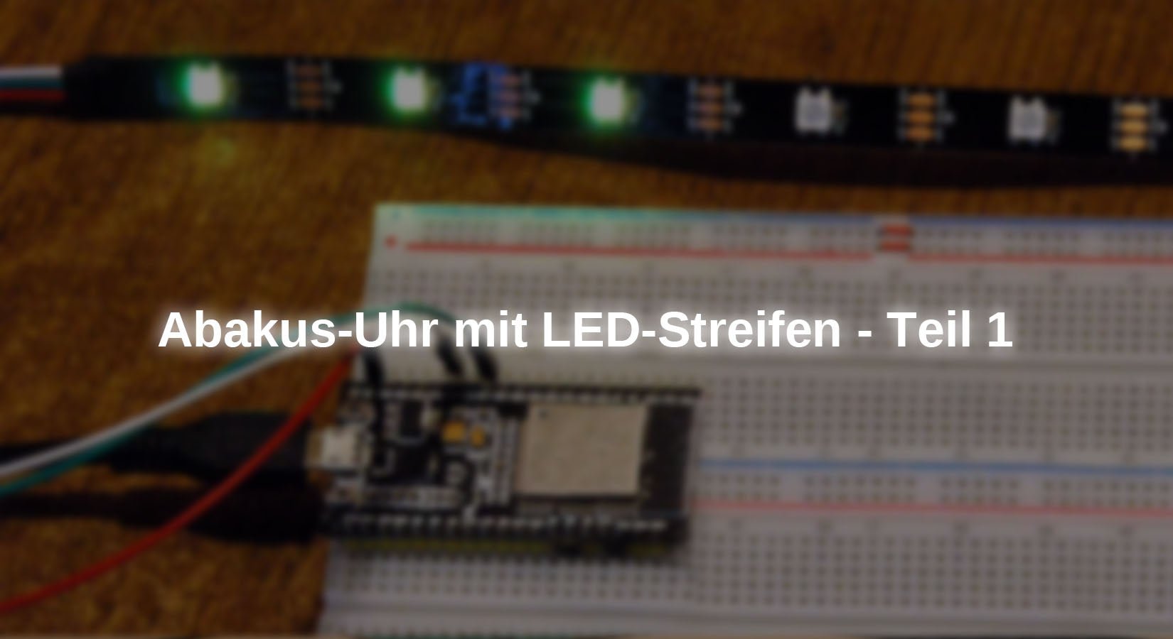
Now that the system is clear, let's move on to the implementation. Figure 5 shows the setup. We read 9 hours (7, 8, 9, because yellow) on the LED strip.

Figure 5: LED-strip-clock_expansion stage 1
The hardware list is not very long.
hardware
|
1 |
ESP32 Dev Kit C V4 unsoldered or ESP32 NodeMCU Module WLAN WiFi Development Board with CP2102 or |
|
1 |
Or |
|
1 |
Or D1 Mini NodeMcu with ESP8266-12F WLAN module compatible with Arduino |
|
1 |
|
|
1 |
Optional for ESP8266 D1 mini and Raspberry Pi Pico Button for example KY-004 Button module |
|
1 |
|
|
Optional |
|
|
Optional |
An ESP8266 would also be sufficient for expansion stage 1. However, with regard to stage 2, in which a BME280 is added, the little one is unfortunately too weak on the memory chest, which is why an ESP32 is already used here. Alternatively, a Raspberry Pi Pico (W) can also take over the control. It should be WLAN-capable because we need a connection to an NTP server on the Internet in stage 2.
With a logic analyzer, the signals on the NeoPixel bus can be visualized very nicely. This is particularly helpful if problems occur or if you want to study the behavior of NeoPixel arrays, as in this article.
The Charger Doctor enables the monitoring/measurement of voltage and current on the USB bus.
Here are the circuit diagrams for the other two controller families.

Figure 6: Abacus clock with ESP8266 D1 mini

Illustration 7: Abacus clock with Raspberry Py Pico W
The control line for the Neopixels is GPIO14 in all cases, so that no changes need to be made to the program, which we will discuss shortly.
The software
For flashing and programming the ESP32:
Thonny or
For displaying bus signals
SALEAE – Logic analyzer software (64 bit) for Windows 8, 10, 11
Firmware used for the ESP8266:
Firmware used for the ESP32:
Firmware used for the Raspberry Pi Pico (W):
RPI_PICO_W-20240602-v1.23.0.uf2
The MicroPython programs for the project:
uhr.py Operating program for the clock
MicroPython - Language - Modules and programs
For the installation of Thonny you will find here a detailed instructions (english version). There is also a description of how the Micropython firmware (as of 25.01.2024) to the ESP chip burned is burned onto the ESP chip. You can find out how to get the Raspberry Pi Pico ready for use here here.
MicroPython is an interpreter language. The main difference to the Arduino IDE, where you always and only flash entire programs, is that you only have to flash the MicroPython firmware once at the beginning on the ESP32 so that the controller understands MicroPython instructions. You can use Thonny, µPyCraft or esptool.py for this. For Thonny I have described the process here described here.
As soon as the firmware is flashed, you can talk to your controller in a casual conversation, test individual commands and see the response immediately without having to compile and transfer an entire program first. This is exactly what bothers me about the Arduino IDE. You simply save an enormous amount of time if you can test simple syntax and hardware tests and even try out and refine functions and entire program parts via the command line before you knit a program from it. I also like to create small test programs for this purpose. As a kind of macro, they summarize recurring commands. Entire applications are then sometimes developed from such program fragments.
Autostart
If you want the program to start automatically when the controller is switched on, copy the program text into a newly created blank file. Save this file under main.py in the workspace and upload it to the ESP chip. The program will start automatically the next time you reset or switch on.
Testing programs
Programs are started manually from the current editor window in the Thonny IDE using the F5 key. This is quicker than clicking on the start button, or via the menu Run. Only the modules used in the program must be in the flash of the ESP32.
In between times Arduino IDE again?
If you want to use the controller together with the Arduino IDE again later, simply flash the program in the usual way. However, the ESP32/ESP8266 will then have forgotten that it ever spoke MicroPython. Conversely, any Espressif chip that contains a compiled program from the Arduino IDE or the AT firmware or LUA or ... can easily be provided with the MicroPython firmware. The process is always the same as here described here.
The ingredients
The local system time
On the ESP32/ESP8266 the time is calculated in seconds from the beginning of the epoch or era. For the ESPs under MicroPython, this is 01.01.2000. You can verify this by selecting the following in the terminal window of Thonny from the module time module the function localtime() function with 0 seconds.
>>> import time
>>> time.localtime(0)
(2000, 1, 1, 0, 0, 0, 5, 1)
This function returns the date, 2000-01-01, and the time (00:00:00). This is followed by the day of the week (5 = Saturday) and the number of the day in the year (1). The values are stored in a Tuple (eng. tuple) are summarized. The order of the individual entries is therefore as follows. DOW stands for Day of Week, DOY for Day of the Year.
Year, month, day, hours, minutes, seconds, DOW, DOY
With the Raspberry Pi Pico (W) the era begins on 01.01.1970.
>>> import time
>>> time.localtime(0)
(1970, 1, 1, 0, 0, 0, 3, 1)
Here is another example that illustrates the relationships. The function time() of the module time module returns the number of seconds since the epoch. The function localtime() converts this value into the date values of the tuple.
>>> time.time()
796996679
>>> time.localtime(time.time())
(2025, 4, 3, 11, 58, 25, 3, 93)
So it is 03.04.2025, 11:58:25 am. The 93rd day of the year is a Thursday. The days of the week are counted from 0 = Monday to 6 = Sunday.
The Real Time Clock - the RTC module
The class RTC lives with the ESPs as well as with the Raspberry Pi Pico in the module machine.
>>> from machine import RTC
>>> RTC
<class 'RTC'>
It represents the method datetime() method, which also returns a tuple with date and time values when called without parameters. However, the order of the parameters differs from that of the time.localtime() function. The day of the week immediately follows the date and the last parameter is not the day of the year, but provides the fractions of a second.
>>> rtc=RTC()
>>> rtc.datetime()
(2025, 4, 3, 3, 12, 53, 36, 400)
If you pass the method datetime() method a tuple of this form, the specification is transparently converted into a seconds timestamp and the RTC is set accordingly. The day of the week and fractions of a second are passed as 0.
>>> rtc.datetime((2022, 12, 4, 0, 9, 6, 41, 0))
>>> rtc.datetime()
(2022, 12, 4, 6, 9, 6, 42, 295)
To convert the RTC format to the format of the time module and vice versa, I have written two functions. These are called module rtc_time.py can be imported into programs. The input and output is in the form of the corresponding tuple.
def time2rtc(t):
Jahr,Monat,Tag,Stunden,Minuten,Sekunden,DOW,DOY = t
return (Jahr,Monat,Tag,DOW,Stunden,Minuten,Sekunden,0)
def rtc2time(r):
Jahr,Monat,Tag,DOW,Stunden,Minuten,Sekunden,ms = r
s=mktime((Jahr,Monat,Tag,Stunden,Minuten,Sekunden,0,0))
t=gmtime(s)
return t
In time2rtc(), the tuple t with the local time is unpacked into individual variables. The day of the week (DOW) is reordered and a 0 is simply returned as the number of milliseconds. RTC cannot do anything with the day number DOY in relation to the year, so DOY ends up in nirvana. The number of milliseconds in the RTC tuple cannot be conjured out of a hat and is therefore simply set to 0.
rtc2time() is somewhat more complex. The RTC tuple is also picked apart first. Then we assemble a tuple of the local time from the data, setting the day of the week and the day of the year to 0. We pass this tuple to the method mktime() method from the timewhich calculates the seconds of the epoch. The method gmtime() method then calculates a time tuple from this again, in which the day of the week and day of the year now appear correctly.
If the module is started as the main program, the following part demonstrates the application. In the attribute __name__ then contains the string "__main__"which leads to the execution of the code in the if block.
if __name__ == "__main__":
from machine import RTC
from time import localtime
r=RTC()
zeit = localtime()
print("lt",zeit)
rt=time2rtc(zeit)
print("rt",rt)
tm=rtc2time(rt)
print("LT",tm)
We import the module RTC module and instantiate an object r. The local time is fetched. The tuple lands in time, is output and passed to the method time2rtc() method, which returns an RTC tuple in RTC format. We also leave this in REPL before passing it to rtc2time() is passed on. The method adds the values for DOW and DOY that have been lost in the meantime to the time tuple that is returned.
lt (2025, 4, 3, 13, 22, 56, 3, 93)
rt (2025, 4, 3, 3, 13, 22, 56, 0)
LT (2025, 4, 3, 13, 22, 56, 3, 93)
We use a timer for the second cycle of our clock. This is to tell the main loop when it is time to send a new constellation to the LED strip. This is where we come across the first difference between the three controller families. The ESP32 has four hardware timers that work independently of the software. With the ESP8266, virtually any number of software timers can be generated, which work on the basis of the RTOS operating system. The same applies to the Raspberry Pi Picowhose any number of software timers use a common hardware timer.
In all cases, the module timer module from the machine module. While the constructor of the timer class is called with a number in the ESP families, the Raspberry Pi Pico leads to an error message. No number must be specified here. We take this into account by comparing it with the variable platform to determine the type of controller.
The neopixel strip
Neopixel LEDs of type WS2812 contain three individual pixels that emit red, green or blue light. They are addressed by a controller that receives its instructions via a type of bus system that is clocked at 800 kHz.
With the I2C bus or the SPI bus, the signals from the controller, for example an ESP32, reach all slaves on the bus in the same way and everyone sees everything. This is different with the WS2812 devices. Each module has a data input and a data output. Several blocks can be cascaded by connecting the data input of each additional block to the data output of its predecessor. The first module in the chain receives a pulse chain of three bytes for R, G and B from the ESP32, which it feeds itself, i.e. removes from the entire pulse train. All subsequent pulses are waved through and output at the data output. Each module in the chain takes its share in the same way and passes on the rest. This makes it possible to control each component in the chain individually. The intensity of each color can be varied in 256 steps, depending on the value of the byte received for each color. We enter the color code in the form of a tuple for each WS2812 as an element of a list in a list. First the classes pin and NeoPixel imported. I create a pin object as an output and use it to instantiate a NeoPixel object with 30 blocks. The NeoPixel instance neo contains a byte array buf and the method write() method, with which the content of the byte array is transferred to the neopixel ring.
>>> from machine import Pin
>>> from neopixel import NeoPixel
>>> np=Pin(14,Pin.OUT) # D5
>>> neo=NeoPixel(np,30)
>>> neo[0]=(0xe0,0x07,0x3c)
>>> neo[1]=(0xf0,0xf0,0xf0)
>>> neo.write()
>>> neo.buf
bytearray(b'\x07\xe0<\xf0\xf0\xf0\x00\x00\x00\x00\x00\x00\x00\x00\x00\x00\x00\x00\x00\x00\x00\x00\x00\x00')
With neo[0] I address the first three elements of the array and pass the values for red, green and blue, 0xe0, 0x07 and 0x3c. Internally, this is done by the private function __setitem__(). The values are entered into the buffer in a different order. As we will see in a moment from the curve that I recorded with the help of the Logic Analyzer. The values are sent as they appear in the buffer. A 0 corresponds to a narrow pulse of approx. 250ns width followed by a pause of approx. 1000ns. The 1 is sent by a pulse of 750ns and a pause of 500ns.

Illustration 1: Pulse sequence for RGB = 0xE0, 0x07, 0x3C
The three bytes 0xe0, 0x07 and 0x3c, which this module has eaten, are missing at the output of the first WS2812. Instead, the code 0xff, 0xff, 0xff comes out, the code for the second function block. For this measurement, the input for channel 1 of the logic analyzer was connected to the input of the first LED, channel 2 to its output.
Now we know how the kangaroo runs on the WS2812 and can turn to the program for the clock.
The program uhr.py
We will now discuss the individual parts of the program clock.py. As already mentioned, we need the modules pin, RTC and timer and NeoPixel. The function exit() function allows us to exit the program in an orderly manner, especially during development. We then determine the controller family and set up the timer accordingly.
from machine import Pin,RTC,Timer
from neopixel import NeoPixel
from time import sleep_ms
from sys import exit, platform
if platform == "esp32":
t0=Timer(0)
elif platform == "esp8266":
t0=Timer(0)
elif platform == "rp2":
t0=Timer()
else:
print("Nicht untersttzter Controller")
exit()
Further objects are set up. The GPIO14 connection for the NeoPixel control line is programmed as an output. In order to be able to control all LEDs during development, we create a NeoPixel object with 30 LEDs. This creates a buffer with 30 x 3 bytes for red, green and blue in the controller's memory, which we can later fill accordingly and then output the content to the strip in one go. We also create an RTC object and the GPIO0 input for connecting the button.
np=Pin(14, Pin.OUT)
n=NeoPixel(np,30)
rtc=RTC()
taste=Pin(0,Pin.IN,Pin.PULL_UP)
Next, we create the framework conditions for processing the time information. The variable dt takes up an RTC tuple. The indices for the hour, minute and second positions are set and the color codes are defined. The flag ticked flag is set when the timer t0 is set to True, until then it remains False.
dt=rtc.datetime()
hor=const(4)
mnt=const(5)
sec=const(6)
high=(0x40,0,0)
low=(0,0,0x40)
lowH=(0x40,0,0x40)
highH=(0x40,0x40,0)
single=(0,0x40,0)
ticked=False
tick() is the callback routine that is executed when the timer t0 is called and the flag ticked flag to True. To make the change available in the main program after the ISR (interrupt service routine) is terminated, the ticked must be declared globally. As an ISR should be kept as short as possible, updating the LED strip is left to the main program. In the parameter t, the operating system passes the number of the timer to the routine. The parameter must therefore be specified, even if we do not make use of it.
def tick(t):
global ticked
ticked = True
Another function ledsOff() is declared, it deletes nbr LEDs of the strip. To do this, the RGB tuples of each LED are set to (0,0,0). write() pushes the buffer to the strip if the function with immediate = True is called. If the optional argument is omitted, then immediate is given the default value Nonewhich is used in the if-query as False in the if query.
def ledsOff(nbr,immediate=None):
for i in range(nbr):
n[i]=(0,0,0)
if immediate:
n.write()
Before entering the main loop, we delete all 30 LEDs with immediate effect and initiate the timer with an expiry time of 1 second = 1000 ms for the continuous run. The timer calls the function tick() function and restarts.
ledsOff(30, True)
t0.init(period=1000,mode=Timer.PERIODIC,callback=tick)
while 1:
The main loop runs continuously and has two tasks to fulfill: updating the LEDs and checking whether the button has been pressed. In the latter case, the LEDs must be switched off and the loop must be exited. If the program is exited by pressing CTRL+C, the LEDs usually remain on because the exit occurs at a random point in the program. This is exactly what we prevent with the key. The LEDs are switched off before the program ends.
What happens if the main loop triggers a timer interrupt via the ticked flag?
if ticked:
ticked = False
dt=rtc.datetime()
Then ticked must be set to False and we must read out the RTC. The current timestamp is stored in the variable dt variable.
We then take care of the number of daylight hours, which we first reduce to 12 hours, daylight hours modulo 12 determines the 12-part division of the 24-hour value supplied by the RTC. We can still tell day and night apart ourselves.
hour=dt[hor] % 12
sColor = lowH if hour <= 6 else highH
ledsOff(30)
The next step is to determine the first or second 6-hour round, which determines the LED color of the display. For each round, we delete the LEDs of the strip to rebuild the configuration.
We start with the hours. For 00:xx, none of the hour LEDs may light up. From 01:00 to 06:59, the LEDs at position 0 to 5 must be in the color lowH for the lower range, for 07:00 to 11:59 in the color highH for the upper hour range. Because the position of an individual LED is difficult to locate, the LEDs are switched on until the desired position is reached. At the fourth hour, 4 LEDs light up in pink (1, 2, 3, 4) and during the ninth hour three LEDs light up in yellow (7, 8, 9). This job is done by the for loops. The hour LEDs have a value of 1. Six must be added to the yellow LEDs.
if 1 <= hour <= 6:
for i in range(1,hour+1):
n[i-1] = sColor
elif 7 <= hour <= 11:
for i in range(7,hour+1):
n[i-7] = sColor
Minutes and seconds are coded in the abacus scheme. Blue and red LEDs have the value 5, the green LEDs have the value 1. Blue codes the values 5, 10, 15, 20, 25, 30, red the values 35, 40, 45, 50, 55. The green LEDs indicate the minute values modulo 5, i.e. they count from 1 to 4. When the counter reaches 5, all 4 green LEDs go out and a blue or red one comes on instead. This corresponds to moving the beads back and forth on the abacus when counting up.

Illustration 8: Counting method with the abacus
The following program sequence models this behavior. We get the minute value from the RTC tuple. The integer division provides the number of 5-minute packets, while the integer division remainder modulo 5 provides the individual minutes 1 to 4. We use the number of 5-minute packets to set the light color, less than or equal to 6 sets blue, otherwise red. The minutes are output from pixel position 6 with the groups of 5, the individual minutes follow from position 12.
FifeMin=dt[mnt] // 5
Minutes=dt[mnt] % 5
sColor = low if FifeMin <= 6 else high
if FifeMin <= 6:
for i in range(FifeMin % 7):
n[i+6]=sColor
else:
for i in range(FifeMin - 6):
n[i+6]=sColor
for i in range(1,Minutes+1):
n[i+5+6]=single
The output of the seconds, which follows from position 16, works in the same way.
FifeSec=dt[sec] // 5
Seconds=dt[sec] % 5
sColor = low if FifeSec <= 6 else high
if FifeSec <= 6:
for i in range(FifeSec % 7):
n[i+16]=sColor
else:
for i in range(FifeSec - 6):
n[i+16]=sColor
for i in range(1,Seconds+1):
n[i+5+16]=single
To ensure that the buffer that we have deleted and then filled is also sent to the LED string, we must use the command n.write() command. To check this, we display the time in REPL. We can safely delete this instruction in production mode.
n.write()
print(dt[hor],dt[mnt],dt[sec])
We are almost finished, all that is missing is the key query.
if taste() == 0:
ledsOff(30,True)
t0.deinit()
break
If the button is pressed, the contact pulls the input GPIO0 to GND potential. If the button is not pressed, the internal pull-up resistor pulls the input to +3.3V. With the ESP32 we do not need an extra button, we use the flash button which is connected to GPIO0. We then switch off all LEDs immediately, deactivate the timer and exit the while loop with break.
When everything is connected and the program clock.py program has been typed in, the first test can begin. I have left the LED strip in one piece for this purpose. Because the hour and 5-minute LEDs at 06:xx are directly next to each other, I have chosen different colors for the hours. If the split strips are on top of each other as shown in Figure 3 or 4, you can of course also set blue and red for the hours in the program.
The LED brightness is reduced to 25% for red, green and blue with 0x40. This results in a current of up to 130 mA. A Charger Doctor module was helpful for the determination. At full load, the measuring device shows 270 mA. This leads to the conclusion that the brightness is not directly proportional to the setting values.
Outlook
The choice of sensors for the three microcontrollers gives free rein to the imagination. For example, the brightness of the LEDs could be automatically adjusted to the ambient brightness using an LDR (Light Dependend Resistor). A brightness sensor of the type GY-302 BH1750which can be connected to the controller via the I2C bus.
In the next installment, we will bring a BME280 on board to measure temperature, air pressure and relative humidity. We will also synchronize the clock with an NTP server via the Internet at certain intervals. This is recommended because the RTC on the controllers is not exactly the yellow of the egg as far as accuracy is concerned.

Illustration 9: Current measurement on the USB with the Charger Doctor


