Le kit de soudure 3D DIY pour sapin de Noël ne dispose que de quelques motifs prédéfinis grâce à son microcontrôleur préprogrammé.
Dans ce blog, vous apprendrez à programmer vous-même le microcontrôleur afin de pouvoir contrôler chaque LED et afficher vos propres motifs sur le sapin.
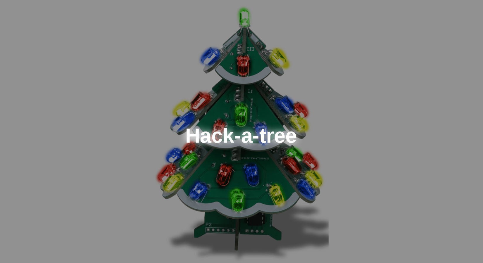
Le blog se réfère exclusivement au kit de soudure 3D DIY Christmas Tree.
1 Informations générales sur le processeur
Le processeur utilisé est un STC15W408 du fabricant chinois STCmicro.
Il est basé sur une architecture (8 bits) 8051 CISC (Complex Instruction Set Computing). Celle-ci a été introduite dès 1980 par Intel. À titre de comparaison, prenons un ATmega328. Celui-ci est basé sur l'architecture AVR RISC (Reduced Instruction Set Computing). La différence concrète réside dans le nombre d'opérations arithmétiques pouvant être effectuées en un cycle. Les processeurs 8051 ont généralement besoin de plusieurs cycles d'horloge pour une opération arithmétique, tandis que leur équivalent AVR n'a besoin que d'un seul cycle pour une opération. Le STC15W408 est toutefois conçu de telle sorte qu'il n'y a pas de différence significative en termes de performances entre les deux processeurs.
Comme mentionné ci-dessus, le STC15W408 est un processeur 8 bits, ce qui signifie qu'une seule opération arithmétique n'est possible qu'avec des valeurs comprises entre 0 et 255. Cela poserait un problème pour les projets complexes, car la vitesse serait considérablement réduite pour les nombres plus élevés. Dans ce cas, il convient d'utiliser des processeurs 32 bits modernes, tels que l'ESP32.
Vous vous demandez peut-être pourquoi un processeur 8 bits tel que le STC15W408 est utilisé dans ce kit. La raison est qu'ici, seules des broches IO individuelles sont commandées et qu'aucun calcul complexe n'est nécessaire pour cela.
Ce processeur est donc idéal pour une telle application, car il est facile à programmer.
Brochage

Illustration 1 : Brochage de la puce
En observant le brochage du circuit, on remarque que les broches IO sont désignées par P0.X à P5.X. Cela s'explique par le fait que le processeur dispose de 5 registres IO P0 à P5. Le chiffre après le numéro de registre représente le numéro de bit dans le registre.

Figure 2 : Broche Registre P1 (extrait de la fiche technique, chapitre 4.7)
2 Connexion des LED
Les cartes comportent 37 LED à effet RVB, mais toutes les LED ne peuvent pas être allumées individuellement. L'image suivante montre les groupes associés sont marqués de chiffres pour faciliter leur attribution.

Illustration 3 : vue latérale avec LED numérotées
Comme cette numérotation des LED est identique de chaque côté de l'arbre, les quatre côtés sont désignés par des lettres afin de pouvoir les distinguer lors du mappage des broches.

Illustration 4 : vue de dessus avec les côtés étiquetés
Le tableau suivant répertorie toutes les broches IO avec la désignation des LED connectées. Les broches IO 1.0 à 1.5 manquantes ne sont pas connectées aux LED.
| 1.6 | A2 | 3.0 | B1 |
| 1,7 | A1 | 3.1 | B2 |
| 2,0 | D3 | 3,2 | B3 |
| 2.1 | D4 | 3.3 | B4 |
| 2.2 | D5 + en haut | 3.4 | B5 |
| 2,3 | A5 | 3,5 | C5 |
| 2.4 | A4 | 3,6 | C4 |
| 2,5 | A3 | 3,7 | C3 |
| 2.6 | D2 | 5,4 | C2 |
| 2,7 | D1 | 5,5 | C1 |
Circuit de réinitialisation
Pour que la puce puisse être flashée, celle-ci doit être être brièvement déconnecté du courant et reconnecté. C'est pourquoi il faut construire un petit circuit à transistor pour le FT232, qui est relié au DTR .
Pour construire le programmateur, vous avez besoin des éléments suivants :
Convertisseur série FT232
Carte perforée min. 8x13 (par exemple, issue de la gamme PCB)
Câbles (par ex. Assortiment de câbles en silicone)
Résistances 470 Ω, 10 kΩ, 100 kΩ (par exemple, de la gamme de résistances)
LED jaune (par exemple, dans la gamme de LED)
Transistor NPN BC547 (par exemple ->Amazon)
(en option : pogopins ou cavalier F2M pour la connexion aux broches UART de l'arbre)

Figure 5 : Circuit du programmateur sur carte perforée

Montez le circuit comme indiqué ci-dessus. Il est recommandé de ne pas souder le connecteur femelle droit directement sur le circuit imprimé si vous n'utilisez pas de broches Pogo, car le programmateur ne pourrait alors pas être branché. Il est également recommandé de relier le connecteur femelle au circuit imprimé à l'aide d'un câble.
Si le programmateur est correctement monté selon le schéma électrique, vous pouvez connecter le kit à l'aide de broches Pogo ou d'un connecteur mâle. Pour ce faire, connectez la carte aux quatre connecteurs situés sous la puce comme suit.
P31 (TX) = RX (FT232)
P30 (RX) = TX (FT232)
3V3 = VCC (FT232)
GND = émetteur transistor
Veillez à ce que le cavalier du FT232 soit réglé sur 3V3, car un niveau logique trop élevé pourrait endommager la puce.
Logiciel
Le STC15W408 n'est pas compatible avec l'IDE Arduino. Le plugin PlatformIO pour VS-Code constitue une bonne alternative à l'IDE Arduino habituel. Il comprend déjà plus de 1 000 cartes différentes, dont les puces STC.
Commencez par installer l'IDE Visual Studio Code. Vous pouvez télécharger le fichier d'installation télécharger ici .
Une fois l'IDE installé et ouvert, accédez aux extensions. Vous pouvez les ouvrir soit via la barre latérale gauche (voir le marquage rouge dans l'illustration), soit via la combinaison de touches Ctrl+Maj+X.

Illustration 6 : Menu Extensions dans la barre latérale gauche
Recherchez ici le plugin Platform IO et installez-le.

Illustration 7 : vue dans la gestion des extensions
Ensuite, ouvrez la page d'accueil de PlatformIO (barre latérale > Platform IO > Quick Access > PIO Home > Open) et cliquez sur « New Project ».

Illustration 8 : configuration du projet
Dans cette fenêtre, vous pouvez maintenant choisir un nom pour le projet et la carte. Ici, vous devez sélectionner le STC15W408AS . Pour finir, confirmez la configuration du projet en cliquant sur le bouton bouton Finish .
Une fois le projet créé, il ne reste plus qu'à ajouter le code. Afin de garder le fichier contenant le code pertinent aussi clair que possible, un fichier d'en-tête externe (.h) contenant toutes les déclarations de registre nécessaires de la puce est utilisé.
Vous pouvez télécharger un fichier adapté à la puce télécharger ici sur GitHub.
Une fois le fichier téléchargé, vous pouvez le placer dans le répertoire src . Créez également un nouveau fichier nommé main.c, dans lequel se trouvera plus tard le programme à exécuter.
Code de test
Pour le premier test, toutes les diodes électroluminescentes doivent être allumées, puis éteintes après un certain délai.
Chargez maintenant le programme suivant sur le microcontrôleur :
| #include |
Le fichier ici .
Explication :
(1) Au début, le fichier d'en-tête contenant les définitions des registres est intégré.
(2) Ensuite, des macros sont définies pour les deux états de la LED. Cela permet d'améliorer la clarté dans la partie routine. Normalement, une LED connectée est allumée par un IO à l'état HIGH, car l'anode (+) de la LED est généralement connectée à l'IO. Sur le circuit imprimé, cependant, la cathode (-) de la LED est connectée à l'E/S, ce qui signifie qu'elle n'est allumée que lorsqu'elle est à l'état LOW.
Comme une LED (diode électroluminescente) est, comme son nom l'indique, une diode, elle est bloquée lorsque l'E/S est à l'état HIGH et ne s'allume donc pas.
(3) Étant donné que le STC15W408 n'intègre pas automatiquement les méthodes standard Arduino telles que delay(), la fonction delay() est ici implémentée.
(4) La boucle de comptage interne nécessite environ une milliseconde pour s'exécuter. Cette boucle s'exécute alors exactement avec le nombre de millisecondes qui a été transmis comme paramètre à la fonction. Il est ainsi possible de réaliser un simple retard, mais celui-ci dépend de la fréquence d'horloge du processeur et peut présenter des écarts en cas de retards plus longs.
(5) L'affectation des registres suivante permet de régler les broches IO en mode push-pull. Cela permet un fonctionnement à courant élevé sur la broche IO. Vous trouverez de plus amples informations dans la fiche technique de la puce aux chapitres 4.9.2 et 4.7 .
(6) Ici, les registres E/S sont réglés sur la valeur HIGH afin que toutes les LED soient éteintes au début.
(7) Dans la boucle, les broches E/S/LED sont activées et désactivées avec une pause de deux secondes.
(8) Outre le réglage d'un registre IO complet, il est également possible de régler des bits individuels dans le registre, qui correspondent aux broches IO individuelles.
Le téléchargement s'effectue simplement en cliquant sur la flèche dans la barre inférieure.
Une fois le téléchargement terminé, le message suivant devrait s'afficher dans le terminal :

Illustration 9 : sortie dans le terminal VS Code
Remarque : lors du premier téléchargement, le fichier stcgal outil automatiquement installé, qui est nécessaire pour flasher la puce.
Conclusion
Après avoir lu cet article, vous êtes désormais en mesure de programmer vous-même le STC15W408 utilisé dans le kit 3D Christmas Tree et d'y afficher vos propres motifs.
N'hésitez pas à expérimenter les innombrables motifs désormais possibles avec le kit.
Amusez-vous bien :)
Les sources suivantes ont été utilisées pour la création du blog :
https://www.stcmicro.com/datasheet/STC15F2K60S2-en.pdf
https://de.wikipedia.org/wiki/Intel_MCS-51
https://de.wikipedia.org/wiki/Reduced_Instruction_Set_Computer
https://de.wikipedia.org/wiki/Complex_Instruction_Set_Computer
Si vous souhaitez approfondir vos connaissances, vous pouvez les consulter. Les référentiels GitHub des deux projets open source stcgal et stc-mcu-open-source sont également intéressants.


6 commentaires
Bastian Brumbi
Hallo zusammen!
Das Fritzing Diagramm habe ich um einen technischen Schaltplan ergänzt.
Der Lautsprecher kann leider aufgrund eines Layout-Fehlers nicht in Betrieb genommen werden. Bei Bedarf können Sie einen passiven Piezo über einen IO anschließen.
@BirgerT Die Leuchtdioden verfügen über einen internen Chip, welcher die Farbabfolge regelt. Dieser kann nicht angesteuert werden!
Birger T
Und wie bekommt man wieder den ursprünglichen Code auf den Controller?
Wie funktionieren die 2-Draht RGB-LEDs – Datenblatt, Type?
Wie (wenn überhaupt) werden die Melodien erzeugt?
Bernd-Steffen Großmann
Ich wiederhole meine Frage nach einem Schaltplan für den Programmerzusatz, da ich das ( fehlerhafte?) Realschaltbild nicht verstehe. Außerdem die Frage wie man den eingebauten Lautsprecher aktivieren kann?
Bernd-Steffen
Hallo, in dem Weihnachtsbaum befindet sich auch ein Lautsprecher. Wie kann der zum Einsatz gebracht werden?
Mfg
Bernd-Steffen Großmann
Hallo Bastian, aus der Fritzing-Anordnung werde ich nicht schlau, wie die Transisorschaltung mit dem Programmer verbunden wird! Wäre es möglich, einen ordinären Schaltplan dazu zu veröffentlichen, damit es auch Old-School-Hobbyisten verstehen?
Peter
The Description is wrong! The ATmega328 is NOT based on the ARM Architecture! It has its own proprietary CPU Architecture named AVR! However it is also an RISC architecture as arm but that is the only common part.