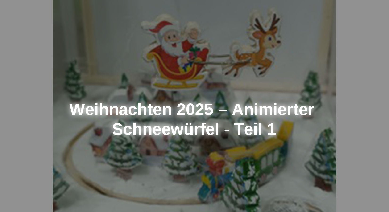
S'il y a un élément particulier dans les décorations de Noël, ce sont probablement les boules à neige de Noël, qui contiennent généralement un bonhomme de neige ou le Père Noël et qui, lorsqu'elles sont secouées, créent une tempête de neige à l'intérieur. Pour Noël de cette année, ils veulent reprendre cette idée, mais en l'adaptant au monde d'Arduino, c'est pourquoi la boule de verre doit être remplacée par une urne transparente. Aucun liquide n'est autorisé à être utilisé, c'est pourquoi des tentatives sont faites pour simuler le blizzard avec des éventails et de petites plumes provenant d'un plumeau. L'animation est assurée par un petit train qui circule à l'extérieur d'un petit village tandis qu'un petit Père Noël survole le village dans son traîneau.
Puisque l'éclairage avec des messages est un incontournable à Noël, Noël sera félicité avec l'éclairage, l'éclairage sera également simulé à l'intérieur de certaines maisons du village, et pour que le projet attire l'attention, il sera accompagné de musique et de sons.
Ce projet de Noël est divisé en deux parties : la première partie consiste à assembler la structure et les éléments du projet et à installer les deux moteurs à courant continu qui déplacent à la fois le train et le Père Noël ainsi que l'éclairage intérieur de certaines maisons du village. Dans la deuxième partie, le projet se complète avec l'installation d'un écran LED WS2812B pour afficher l'actualité, la sonorisation et les fans.
Les matériaux nécessaires à l'ensemble du projet sont :
● 1 Carte microcontrôleur AZ-ATmega328
● 1 Module de carte de contrôleur de moteur à courant continu à Double pont en H AZ-L298N
● 1 Modules principaux pour mini lecteur MP3
● 1 PAM8403 mini amplificateur audio numérique carte 2x3 watts DC 5 V avec potentiomètre
● 2 mini haut-parleurs 3 watts 8 ohms
● 1 Module relais 4 canaux 5V avec déclencheur de bas niveau par optocoupleur
● 2 Moteur à engrenages TT Motor DC3V-6V, double arbre
● 1 Potentiomètre 5 Kohm
● 1 Panneau LED RVB WS2812B 16x16 256 LED
● Câble de raccordement 3 x 40 pièces. 20 cmM2M/F2M/F2F
● Platine d'essai MB-102 avec 830 contacts
● Panneaux de contreplaqué, bois, 420 x 300 x 3 mm
● EDI Arduino
● Bibliothèque Adafruit GFX (Arduino Adafruit_GFX.h)
● Bibliothèque Adafruit NeoPixel (Arduino Adafruit_NeoPixel.h)
● Bibliothèque SoftwareSerial (LogicielSerial.h)
● Bibliothèque Adafruit_NeoMatrix (Adrafruit_NeoMatrix.h)
● Mini bibliothèque DFPlayer de DFRobot (DFRobotDFPlayerMini.h)
● Bibliothèque SPI.h (incluse dans l'IDE Arduino)
● 001.mp3
● 002.mp3
● 003.mp3
● snow_cube_animated_part_1.ino
Les dessins des personnages sont :
● Zug.jpg
Schéma de circuit et description des modules utilisés dans le projet final

Dessin 2 – Dessin de cube de neige, partie 2
Comment fonctionne le projet
Lorsque la deuxième partie du projet sera terminée et opérationnelle, le train circulera dans un sens tandis que le Père Noël voyagera dans le sens opposé alors qu'il neige dans le petit village. En arrière-plan du paysage se trouve une matrice LED qui affiche le message de félicitations. Des images peuvent également être affichées si vous le souhaitez. Pendant le fonctionnement, le bruit du train, le tintement des cloches des rennes du Père Noël et la musique de Noël alternent. Les fichiers musicaux peuvent être personnalisés. Des fichiers libres de droits ont été téléchargés dans ce projet.
Pour déplacer le train et le traîneau du Père Noël, des moteurs à courant continu sont utilisés. Une roue de 6 mm d'épaisseur avec un bord en caoutchouc a été couplée au moteur qui entraîne le train, qui fait tourner un anneau en bois sur lequel le train est installé. Pour le mouvement du Père Noël, un fil est attaché, à une extrémité duquel le Père Noël est attaché et l'autre extrémité doit être installée sur l'axe du moteur. Les deux moteurs sont alimentés et contrôlés par le module de commande de moteur L298N. De petits morceaux de plumeau ont été utilisés pour créer l’effet neige car ils sont très légers et peuvent être facilement déplacés avec un flux d’air minimal. Nous utilisons quatre ventilateurs 5VDC pour souffler de l'air dans la capsule. Ces moteurs sont alimentés via le module 4 relais. Un module relais protège le microcontrôleur des surcharges et des pics de courant lors du démarrage. Une matrice LED RVB 16x16 est utilisée pour les affichages lumineux. En modifiant le croquis, des images peuvent également être affichées. Une combinaison d'un lecteur MP3, d'un amplificateur et de deux haut-parleurs est utilisée pour le son. Pour simuler l'éclairage intérieur des maisons du village, 6 LED blanches de 3 mm sont utilisées dont chacune doit être connectée à une résistance de 330 ohms pour régler la tension d'alimentation. Le microcontrôleur AZ-ATmega328 a été utilisé pour contrôler toute l'électronique.
Assemblage du projet
Les figurines et la structure ont été réalisées en bois de balsa de 3 millimètres d'épaisseur, car ce matériau permet toutes les modifications nécessaires à la structure pour corriger le projet et est également très léger et facile à manipuler. Les dimensions des figures et la structure de ce projet sont indicatives et peuvent être ajustées aux dimensions souhaitées.
Pour construire le train, deux dessins de chaque wagon et locomotive ont été collés en bois de balsa et leurs contours ont été découpés. Afin de pouvoir placer le train sur l'anneau, il a été décidé de coller un fil de fer entre les deux parties de chaque figurine de train. Cela a été fait en redressant un trombone pour attacher les deux parties de la figurine et en faisant une encoche de 1 mm de profondeur dans chaque partie de la figurine afin que le fil reste en place lors du collage des deux parties ensemble. Les dimensions et la méthode de fabrication du train sont visibles sur la photo ci-dessous.

Figure 1 – Dimensions et structure du train
Il a déjà été mentionné que certaines maisons du village disposeront d'un éclairage intérieur. A cet effet, des LED blanches seront installées dans six maisons. Pour construire le village, on utilise la même méthode que pour le train : on dessine les silhouettes des maisons à coller. mais avant cela, les contours sont découpés, les rainures sont créées pour l'installation des LED et des câbles de connexion et les trous pour les fenêtres et les portes sont percés afin que la lumière des LED brille à travers le papier lorsque les contours des maisons sont collés. Les dimensions des maisons peuvent être librement ajustées.

Image 2 – Ville
La méthode de construction de la figurine du Père Noël est similaire à celle du train : les contours de la figurine du Père Noël et du renne sont marqués, cette fois le Père Noël et les rennes sont reliés par deux fils, qui sont attachés de la même manière aux wagons. Le fil qui relie le Père Noël au moteur qui le fait tourner est attaché à l'arrière du traîneau puis plié à angle droit pour le guider jusqu'à l'essieu du moteur.

Image 3 – Dimensions du Père Noël
La méthode de construction des figurines de sapin de Noël est similaire aux précédentes : les contours des figurines de sapin de Noël sont marqués et les figurines sont collées. Vous pouvez utiliser deux contours et les relier ensemble ou simplement utiliser un contour en bois et coller le dessin du sapin de Noël des deux côtés.

Image 4 – Arbres de Noël
Pour assembler le train sur l'anneau, les rainures nécessaires sont réalisées dans la zone centrale entre les deux bords des anneaux, afin de former ensuite deux angles de 90 degrés sur les câbles des wagons et de la locomotive et de les installer sur les anneaux. Les photos montrent les dimensions de l'anneau, la forme donnée aux fils pour incorporer la traction dans l'anneau et l'état final de l'anneau.

Figure 5 – Anneau de traction
Pour construire la plate-forme sur laquelle se dressera le village, on découpe un cercle dont le diamètre doit être légèrement supérieur au diamètre intérieur de l'anneau. Comme on peut le voir sur les images ci-dessous, des trous seront pratiqués pour passer les câbles de connexion aux LED qui éclaireront l'intérieur des maisons du village, ainsi que trois fentes pour insérer la partie supérieure des colonnes qui fixeront la plateforme du village à la structure du projet. Ces colonnes ont la même hauteur que les colonnes extérieures de la boîte à projet. À l'intérieur de la plate-forme, 3 broches en bois sont placées de manière à ce qu'elles soient à l'intérieur de l'anneau et aient un jeu d'environ 2 millimètres pour que l'anneau puisse tourner librement et servent de limite à un éventuel déplacement latéral de l'anneau.

Image 6 – Quai du train urbain
Afin d'accueillir les ventilateurs, les sapins et le moteur qui fera tourner l'anneau du train, il a été prévu de réaliser un cube avec un cercle au sommet d'un diamètre inférieur au diamètre extérieur de l'anneau, gardant ainsi l'anneau contenant le train dans les limites du quai du village et de la plate-forme des ventilateurs et des sapins. Le train traverse l'espace libre d'environ 4 millimètres de large. Ce projet a utilisé des colonnes de même hauteur que les colonnes de support de la plateforme du village. Il y en avait trois par côté (sur les bords et au milieu des pages). Le lecteur peut également utiliser des colonnes ou des plaques aux dimensions requises pour les recouvrir. La figure suivante montre les dimensions de toutes les pièces de ce composant.

Figure 7 – Plateforme des fans
Les images suivantes montrent les étapes d'assemblage de la première partie du projet, qui consiste à installer la plateforme du village, l'anneau de traction et la plateforme avec les ventilateurs et les sapins. Comme vous pouvez le voir sur la dernière photo, tout a été peint au feutre blanc pour simuler un paysage enneigé.

Image 8 – Assemblage de la première partie du projet
Description du fonctionnement de la première partie du projet et esquisse
Pour cette première partie du projet, l'électronique de base pour le déplacement du train et du Père Noël a été installée, ainsi que l'éclairage intérieur de certaines maisons, 6 maisons pour être précis. Le circuit électronique est structuré comme suit :

Dessin 1 – Dessin de cube de neige, partie 1
Le circuit de la première partie du projet dispose du module de commande de moteur L298N pour contrôler la vitesse et le sens de rotation des deux moteurs de l'ensemble, dont l'un est chargé de déplacer l'anneau avec le train et l'autre de déplacer le Père Noël. Ce module est alimenté avec deux tensions : l'électronique de commande du module est alimentée via la sortie 5 VDC du module microcontrôleur, et les moteurs sont alimentés via une alimentation externe 5 volts. Il faut prendre soin de retirer le cavalier qui désactive le contrôleur interne du module.

Figure 9 – Module L298N
Il y a 6 LED blanches de 3 millimètres qui doivent avoir une résistance de 330 ohms connectée à la borne positive de chaque LED. Cette résistance régule la tension nécessaire pour alimenter la LED sans la détruire par surtension. Les LED seront installées dans 6 maisons comme éclairage intérieur.
Nous allons maintenant analyser le croquis de la première partie. Tout d'abord, les broches du microcontrôleur doivent être définies dans le croquis auxquelles seront connectés les contacts du module L298N qui contrôle chaque moteur. Pour chaque moteur, nous avons besoin de trois ports, un contrôlant la vitesse du moteur et les deux autres contrôlant le sens de rotation. Celui-ci définit six constantes auxquelles sont attribuées le numéro du port du microcontrôleur auquel les broches ENA, IN1, IN2, IN3, IN4 et ENB du module L298N sont connectées. Les noms des constantes permettent d'interpréter facilement les moteurs qu'elles représentent.
#define activer_Santa_motor 7
#define connexion_1_Santa_motor 5
#define connexion_2_Santa_motor 6
#define activer_train_moteur 2
#define connexion_1_train_moteur 3
#define connexion_2_train_moteur 4
De plus, des constantes doivent être définies pour les six LED, auxquelles sera attribué le numéro du port du microcontrôleur auquel elles seront connectées.
#define led_house_1 8
#define led_house_2 9
#define led_house_3 10
#define led_house_4 11
#define led_house_5 12
#define led_house_6 13
Avec les définitions des constantes, le bloc de définition des variables et la méthode sont complétés configuration() du croquis doit être programmé. Tout d’abord, les broches du microcontrôleur qui serviront à contrôler les moteurs sont configurées. Tu dois venir avec moi mode broche(numéro_pin, SORTIE) configurées comme broches de signal de sortie car elles doivent envoyer des signaux aux broches du module de commande L298N.
mode broche(enable_Santa_moteur,SORTIE);
mode broche(connection_1_Santa_motor,SORTIE);
mode broche(connection_2_Santa_motor,SORTIE);
mode broche(enable_train_motor,SORTIE);
mode broche(connexion_1_train_moteur,SORTIE);
mode broche(connexion_2_train_moteur,SORTIE);
Les broches du microcontrôleur auxquelles les LED sont connectées doivent également être configurées comme broches de sortie, car elles doivent fournir une tension pour que les LED s'allument.
mode broche(led_house_1,SORTIE);
mode broche(led_house_2,SORTIE);
mode broche(led_house_3,SORTIE);
mode broche(led_house_4,SORTIE);
mode broche(led_house_5,SORTIE);
mode broche(led_house_6,SORTIE);
Les lignes ci-dessus servent à programmer la méthode configuration() du croquis terminé. Maintenant, la méthode doit boucle() programmé pour fonctionner en continu. Les trois premières lignes de cette méthode sont utilisées pour contrôler le moteur du Père Noël, la ligne analogWrite(numéro_pin, valeur) Le régime moteur est réglé avec une valeur analogique dont la valeur maximale est de 244. Comme on peut le voir dans la vidéo de cette première partie, le régime moteur est trop élevé. Si la valeur de cette variable est inférieure à 128, le moteur ne tournera pas. La deuxième partie du projet résout ce problème en ajoutant un potentiomètre. Les deux servent au sens de rotation du moteur écriture numérique(numéro_pin, état) des lignes définies sont utilisées. Si le moteur du Père Noël tourne dans le sens opposé au sens souhaité, cela peut être corrigé soit en changeant l'état de ces deux fils, soit en intervertissant les câbles du module L298N au moteur.
analogWrite(enable_Santa_moteur,128);
écriture numérique(connection_1_Santa_motor,ÉLEVÉ);
écriture numérique(connection_2_Santa_motor,FAIBLE);
Les lignes de code permettant de contrôler le moteur de la bague de traction sont exactement les mêmes que celles expliquées précédemment. Dans ce cas, la vitesse du train est correcte. Si vous souhaitez une vitesse plus élevée, vous devez définir la valeur dans la ligne analogWrite(numéro_pin, valeur).
analogWrite(enable_train_motor,128);
écriture numérique(connexion_1_train_moteur,ÉLEVÉ);
écriture numérique(connexion_2_train_moteur,FAIBLE);
Pour que les LED s'allument, il faut changer l'état des broches auxquelles elles sont connectées. Normalement, lors de la mise sous tension d'une carte microcontrôleur ou d'une réinitialisation, l'état initial des ports est faible (FAIBLE), C’est-à-dire qu’ils ne fournissent aucune tension, donc l’état est « élevé » (ÉLEVÉ) doit être modifié pour obtenir une tension de sortie de 5 Vdc. Cela se fait avec la commande écriture numérique(numéro_pin, ÉTAT). Il y aura une pause de 3 secondes après que chaque LED s'allume.
écriture numérique(led_house_1, ÉLEVÉ);
retard(3000);
écriture numérique(led_house_2, ÉLEVÉ);
retard(3000);
écriture numérique(led_house_3, ÉLEVÉ);
retard(3000);
écriture numérique(led_house_4, ÉLEVÉ);
retard(3000);
écriture numérique(led_house_5, ÉLEVÉ);
retard(3000);
écriture numérique(led_house_6, ÉLEVÉ);
retard(3000);
Nous espérons que vous avez apprécié cette première partie du projet pour Noël cette année. La deuxième partie du projet consistera à installer un panneau WS2812B doté de 256 LED, un système audio et des ventilateurs pour simuler la neige.


