
This article is also available as PDF document for download.
Do you know a sensor that can measure analog voltages on 4 ports, send PWM signals on 6 lines, and serve 18 digital IO lines? And all that with a single device! Moreover, the little thing can be contacted via I2C. One can realize an "intelligent" keyboard with it, which offers a key query with timeout and surely a whole lot more!
There is no such thing, you think? Well, then I invite you to join me on this tour through the blog post from the series
MicroPython on the ESP32 and ESP8266
To accompany me, Image 2 and the subtitle may already give you an idea of what to expect.

Image 1: Universal sensor actuator port extension
Arduino goes ESP8266/32 via I2C (part 4)
The little thing on the bottom right of the breadboard not only looks like a Nano V3, but it is also one and exactly that is the star of today's post, next to the ESP8266-01 in the lower left corner of the development board.
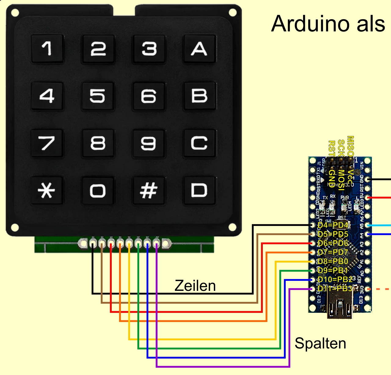
In the previous episode, I covered the hardware and its connection to the I2C system. Nothing has changed on the parts except for the addition of the 4x4 matrix keypad, an LED, and the associated resistor, but the wiring has.

Figure 2: IO ports and PWM LED control
Hardware
|
1 |
|
|
1 |
|
|
1 |
|
|
2 |
|
|
1 |
|
|
1 |
|
|
1 |
|
|
1 |
|
|
1 |
|
|
3 |
|
|
1 |
|
|
1 |
|
|
various |
|
|
2 |
suitable USB cables |
|
1 |
battery 4,5V or 5V wall adapter |
(*) alternative possibility further down in the text
In the last episode I already pointed out that if you care about the life of your ESP8266-01, you have to keep voltages higher than 3.6V away from its tentacles. This concerns the supply voltage from the FTDI232 adapter, but also the I2C lines to the microcontroller. Therefore there is also a level shifter as an interpreter, which translates the signals on the bus between 5V and 3.3V. If you don't have such a module at hand, a setup with discrete components will also help. The following circuit diagram shows the connection.

Image 3: Level shifter with CMOS transistor
The two N-channel MOSFETS 2N7000 convert a 5V pulse into a 3.3V pulse and vice versa. Other MOSFETs can be used if their gate-threshold voltage is lower than the 3.3V of the supply voltage, as in the 2N7000 (2.1V).
Important: the source connection of the transistor must be on the side with the lower supply voltage.
Once again to repeat: The AVR controller ATMega328 on the Nano V3 has three groups of IO connectors, PortB, PortC, and PortD. The designations on the board differ from these. I come from the assembler side and am therefore at home with the designations B, C, and D. For us the correct assignments are important now because we need them later in the programming. We address whole ports here and not single lines, this has some advantages.
|
AVR Port |
PD0 RXD |
PD1 TXD |
PD2 |
PD3 |
PD4 |
PD5 |
PD6 |
PD7 |
|
Nano V3 |
D0 RXD |
D1 TXD |
D2 |
D3 |
D4 |
D5 |
D6 |
D7 |
|
AVR Port |
PB0 |
PB1 |
PB2 |
PB3 |
PB4 |
PB5 |
|
Nano V3 |
D8 |
D9 |
D10 |
D11 |
D12 |
D13 |
|
AVR Port |
PC0 |
PC1 |
PC2 |
PC3 |
PC4 |
PC5 |
|
|
|
Nano V3 |
A0 |
A1 |
A2 |
A3 |
A4 |
A5 |
A6* |
A7* |
* Only TQFP variant and only analog inputs there as well
Each port group has three registers, an output register called PORT, an input register PIN, and a data direction register DDR. Our goal is to describe and query all three types in full width. Also, single, specific bit operations should be possible. Commands and data travel over the I2C bus, the ESP8266-01 is the client.
Group C dances a bit out of line. The C-lines serve their function as digital ports and also as inputs of the analog multiplexer which in turn feeds the signals to the ADC (analog-to-digital converter). We will use input A3 in this sense today. A4 and A5, aka PC4 and PC5, provide the connection to the I2C hardware. On the Nano V,3 the functions of this interface are realized by hardware.
So that we can check the control of the ports, we connect an RGB LED via three resistors to certain IO lines. Ports PC0 (blue), PC1 (green), and PC2 (red) are used for this purpose.
The software
For flashing and programming the ESP32:
Thonny or
For the Nano V3
arduino_as_slave.ino For communication with the ESP8266-01 and for processing commands
Used firmware for the ESP8266/ESP32:
Please choose a stable version
The MicroPython programs for the project:
esp_i2c_master.py: For communication with the Nano V3
MicroPython - Language - Modules and programs
For the installation of Thonny, you find here a detailed manual. In it there is also a description of how the MicropythonFirmware (as of 02/03/2022) on the ESP chip. burned is burned.
MicroPython is an interpreter language. The main difference to the Arduino IDE, where you always and only flash whole programs, is that you only have to flash the MicroPython firmware once at the beginning to the ESP32 so that the controller understands MicroPython instructions. You can use Thonny, µPyCraft, or esptool.py to do this. For Thonny, I have described the process here described here.
At this point a few words about flashing the ESP8266-01. Unlike its bigger siblings, the ESP8266-01 has no automatic flashing on board. Manual work is required here.
The flash process is divided into two parts, first, erase flash memory and second transfer firmware. The following list is an excerpt from the Description of the flash process:
- a) Complete the preparations in Thonny
- b) Press the reset and flash button
- c) Start the flash process in Thonny
- d) Release the reset key, and hold the flash key until progress is displayed
- e) Release flash key
- f) Wait until access to the COM interface is reported again.
- g) Then go through the points b) to f) again and
- h) Finally close the installer window and exit the options with OK.
Once the firmware is flashed, you can casually talk to your controller one-on-one, test individual commands, and immediately see the response without having to compile and transfer an entire program first. In fact, that's what bothers me about the Arduino IDE. You simply save an enormous amount of time if you can do simple tests of the syntax and the hardware up to trying out and refining functions and whole program parts via the command line in advance before you knit a program out of it. For this purpose, I also like to create small test programs from time to time. As a kind of macro, they summarize recurring commands. From such program fragments sometimes whole applications are developed.
Autostart
If you want the program to start autonomously when the controller is switched on, copy the program text into a newly created blank file. Save this file as boot.py in the workspace and upload it to the ESP chip. The program will start automatically at the next reset or power-on.
Test programs
Manually, programs are started from the current editor window in the Thonny IDE via the F5 key. This is quicker than clicking on the Start button, or via the menu Run. Only the modules used in the program must be in the flash of the ESP32.
In between times Arduino IDE again?
If you want to use the controller together with the Arduino IDE again later, simply flash the program in the usual way. However, the ESP32/ESP8266 will then have forgotten that it ever spoke MicroPython. Conversely, any Espressif chip that contains a compiled program from the Arduino IDE or the AT firmware or LUA or ... can easily be flashed with the MicroPython firmware. The process is always here described.
For the Nano V3, we need of course the Arduino IDE. Here comes a quick guide for the installation of the same.
Setting up the Arduino IDE
If you have not yet worked with the Arduino IDE and this tool is not yet on your computer, please follow this quick guide.
Start with the Download the installation file via this link.

Image 4: Download Arduino IDE
Click the version that corresponds to your operating system and save the file in a directory of your choice.

Image 5: Save the installation file
Start the installation file and follow the user guide. We do not need any external libraries for the Arduino for this project and are ready to go with this.
In both software parts, the individual tasks are outsourced to functions. This keeps the main loop clearer and makes the whole program easier to maintain. Let's start with the MicroPython program for the ESP8266-01 and discuss the changes that have taken place since the previous version.
The ESP8266-01 with the changes and extensions
First of all, after flashing the firmware, we should get the ESP8266 out of the habit of searching for an access point, because in my experience this leads to strangely stubborn behavior of the module.
On the command line of Thonny, we enter the following command and then "d" for disable. This action should be performed every time (only once) after flashing the firmware.
>>> import webrepl_setup
WebREPL daemon auto-start status: disabled
Would you like to (E)nable or (D)isable it running on boot?
(Empty line to quit)
> d
No further action required
In the previous episode, I briefly presented thoughts on the way a program should be designed. It is obvious that a design in which all structures and commands are placed in the main loop is very confusing and therefore difficult to read and maintain.
Equally confusing is a long list of jumps from the main loop to an equally long sequence of mini-procedures that perform individual jobs. Combining jobs and branching into procedures to handle all cases is also counterproductive because it bloats the procedures. Long parameter lists in the calls and hard-to-maintain function bodies are not the best things either.
For this project, as the complexity of the tasks increased, I tried to find a compromise. And I think I have found a workable solution, which also reflects the assembler notation for port access. Assembler instructions with register or memory accesses are read as well as assignments in the high-level languages, from right to left. But see for yourself.
I have combined the functions for port-wide access to the IO area into a single method each. Method, not procedure or function? Pardon, yes, respectively no. I've put all the functions and constants from the last episode into a module called arduino_i2c.py in the meantime. And in the context of the class ARDUINO in it, functions are called methods. The class allows me to use tools in any number of projects. Nevertheless, I have to maintain the file only in one place.
So the syntax (aka notation) of the method calls leans on the assembler notation.
Assembler:
out PORTC, 0x07 # write 0x07 to the PORT register of the PortC group
The method from the ARDUINO class
ARDUINO.writeIO(PORT,C,0x07)
And what the Nano V3 does after receiving the command looks like this:
PORTC=0x07
You can surely see the advantage of this access over the usual approach of operating individual pins separately. By the way, PORTC=0x07 is a command that is available by default in the Arduino IDE, without importing any libraries. But unfortunately I can't find that directly in the language reference of the Arduino crew. It's just strange that this is officially obfuscated. Grouch aside, what's new?
How does a module with a class arise from a loose sequence of constant definitions and functions?
The constants got growth in the commands and in the data direction. The port group has been trimmed down by the DDRs. For comparison I ask, for the file esp_i2c_master.py to download. In U0 is the value of the supply voltage at the 5V pin of the Nano V3, which is determined with a DVM (aka digital volt meter) and should be about 5V as a rule.
 from time import sleep
 HWADR=const(0x24)
 # Port groups
 B=const(0); C=const(1); D=const(2)
 # Commands
 WRITEPORT=const(0)
 WRITEDDR =const(1)
 READPORT =const(2)
 READDDR  =const(3)
 GETKEY   =const(4)
 ANALOGOUT=const(5)
 ANALOGIN =const(6)
 # Data direction
 PIN =const(0)
 PORT=const(1)
 DDR =const(2)
 # Operating voltage of the Arduino
 U0  =4.8
Next is the class definition and the coding of the constructor __init__(). In the program, it will be called later by the name of the class. The constructor is the routine that creates an object, also called an instance, of this class. Here initial values are set and instance variables are created, which can be used by the methods (=functions) of the class. So our class is called ARDUINO. Similar to the while loop or the method declaration, a step is indented after the declaration of the class.
 class ARDUINO:

     def __init__(self,i2c,hwadr=None,u0=None):
         self.i2c=i2c
         if u0 is not None:
             self.U0 = u0
         else:
             self.U0 = U0
         if hwadr is None:
             try:
                 self.hwadr==i2c.scan()[0]
             except:
                 self.hwadr=HWADR
         else:
             self.hwadr=hwadr
         print("Constructor of Arduino-Interface")
         print("Arduino @ {:#x}".format(self.hwadr))
When instantiating an ARDUINO object, the I2C object to be created in the main program is passed. When calling the constructor, the hardware address of the Arduino slave can be passed. If the parameter hwadr is not specified in the call, then i2c.scan() searches for the target, or the default value 0x24 is used if the scan fails. We handle this with try-except. Similarly, the value for the operating voltage of the Nano V3 is set. The results are communicated to us by the print commands.
Surely you are familiar with the parameter self parameter in the parameter list. This is to be understood in such a way that with it a reference (aka reference, addressing) is passed on to the created object. All variables and methods within the generated class instance receive thereby binding and encapsulation this object. That separates it from any further instances of the same class.
writeReg() and readReg() are now called methods. For both the code remains the same except for the additional self the code remains unchanged. By referring to the object itself through self, the i2c instance becomes available anywhere in the methods of the class without having to be passed in a parameter list.
def writeReg(self,command,port,value):
buf=bytearray(3)
buf[0]=command
buf[1]=port
buf[2]=value
written=self.i2c.writeto(self.hwadr,buf)
return written
def readReg(self,command,port,direction=PIN):
buf=bytearray(3)
buf[0]=command
buf[1]=port
buf[2]=direction
written=self.i2c.writeto(self.hwadr,buf)
sleep(0.1)
return self.i2c.readfrom(self.hwadr,1)
We can evaluate the two methods as a link between the I2C interface with its methods and the methods of our application. Both methods work with data structures that are based on the bytes protocol during transmission, but they accept integer values that they convert into a byte array for transmission.
Now it becomes interesting the methods for access to the ports.
     def writeIO(self,reg,port,value):
         assert port in range(3)
         assert value in range(256)
         assert reg in [PORT,DDR]
         try:
             if reg==PORT:
                 written=self.writeReg(WRITEPORT,port,value)
             else:
                 written=self.writeReg(WRITEDDR,port,value)
         except:
             pass
         return written
The method writeIO() combines the write commands to port and DDR registers. Compared to the previous versions, which are still distinguished between PORT and DDR, memory space has been saved because less program text is involved. This was bought by the parameter reg parameter, which was added to the list. This is well justifiable because thereby some program lines could be saved. At the same time, their plausibility check was simplified. The try-except structure was only slightly extended by the if structure, which now serves PORTs and DDRs. Nevertheless, this procedure saves the definition of a complete second routine.
Similarly, the methods readIO(), setBit() and getBit().
     def readIO(self,reg,port):
         assert port in range(3)
         assert reg in range(3)
         content=None
         try:
             if reg==PIN:
                 content=self.readReg(READPIN,port,PIN)
             elif reg==PORT:
                 content=self.readReg(READPORT,port,PORT)
             else:
                 content=self.readReg(READDDR,port)
         except:
             pass
         return content
The method setBit() requires beside self four arguments. Because it can set bits not only to 1 but also to 0, this value must be specified in addition to the bit position. By using the parameter reg must be specified within setBit() it is no longer necessary to distinguish between PORT and DDR. We leave that to the methods readIO() and writeIO(). This shortens the program text from 15 to 10 lines.
     def setBit(self,reg,port,pos,val):
         assert val in range(2)
         assert reg in [PORT,DDR]
         assert port in range(3)
         cont=self.readIO(reg,port)[0]
         if val==1:
             cont |= 1<<pos
         else:
             cont &= 255-(1<<pos)
         self.writeIO(reg,port,cont)
Also getBit() has been improved. Instead of serving only PORT and DDR with 8 lines, the remaining 6 lines also manage to include PIN.
     def getBit(self,reg,port,pos):
         assert reg in [PIN,PORT,DDR]
         assert port in range(3)
         cont=self.readIO(reg,port)[0]
         cont &= 1<<pos
         return cont>>pos
So much for the conversion of the existing program to module and class. But there are also some extensions. There are for example the methods voltage(), readAnalog() and writeAnalog.
voltage() is used to tell the program the value of the operating voltage of the AVR measured with a voltmeter. It is important for the correct calculation of the voltages measured with the analog inputs. Called without an argument, the method returns the value in memory. If a voltage value is passed during the call, the method writes it to the instance variable U0. Example:
 >>> a.voltage()
 4.73
     def voltage(self,value=None):
         if value is not None:
             self.U0=value
         else:
             return self.U0
The name of readAnalog() is similar to the command analogRead() of the Arduino IDE, but was deliberately changed so that the environment can be clearly assigned. In line, the number of analog input at the Nano V3 is specified. If the optional parameter voltage has the value True then a voltage value in volts is returned. True is the default value that is used if the argument is omitted from the call. The parameter digits are also optional and default to 2 decimal places if this parameter is omitted from the call.
     def readAnalog(self,line,voltage=True,digits=2):
         buf=bytearray(2)
         buf[0]=ANALOGIN
         buf[1]=line
         written=self.i2c.writeto(self.hwadr,buf)
         sleep(0.1)
         low,high=self.i2c.readfrom(self.hwadr,2)
         counts=low+256*high
         if voltage:
             pot=10 ** digits
             return int(self.U0*counts/1023*pot) / pot
         else:
             return counts
With the transmission of orders to the Nano V3 we are already familiar with. We fill the send buffer with the values of the arguments, send the mail and after a short breather we fetch the measured value. The 16-bit value comes in the form of two bytes in little-endian format. This means that the lower-order byte LSB arrives before the higher-order MSB. In counts the two are put together again.
If voltage is True, we calculate from the count value of the ADC and the value of the operating voltage in self.U0 the value of the measured voltage, which is then finally rounded to the desired number of decimal places. If is voltage False, simply the count value of the ADC is returned.
The ATMega328 cannot output a programmed, smooth DC voltage, because it does not have a DAC (digital-to-analog converter). But it can output square pulses of different length but fixed frequency via PWM channels 3, 5, 6, 9, 10 and 11. This runs under the name Puls-Weiten-Modulation. LEDs or DC motors, which are controlled with such a signal, react with different brightness of light emission or changed speed. Examples will follow later.
     def writeAnalog(self, line, value):
         buf=bytearray(4)
         buf[0]=ANALOGOUT
         buf[1]=line
         buf[2]=value & 0xFF
         buf[3]=(value >> 8) & 0xFF
         written=self.i2c.writeto(self.hwadr,buf)
         return written
The values for value can go from 0 to 255 for all channels by default. But you can increase this resolution if you fiddle a bit with the timer registers of the ATmega328. Then you can also change the clock frequency of the PWM signal. Unfortunately this is only possible for the PWM outputs D9 and D10 with the methods resolution() and prescalar().
The resolution at D9 and D10 can be 8, 9, or 10 bits. We pass these values to the method call. The method first checks for compliance with the range, then feeds the array with the command RESOLV and the resolution value in val and sends the array to the Nano V3. What the V3 does with it, we will see later.
     def resolution(self, val):
         assert val in range(8,11)
         buf=bytearray(2)
         buf[0]=RESOLV
         buf[1]=val
         written=self.i2c.writeto(self.hwadr,buf)
         return written
Similarly, the method prescaler(). It takes one of the values from the table and sends the index of this value. Invalid parameter values are sorted out.
     def prescaler(self,val):
         values=[0,1,8,64,256,1024]
         try:
             psFactor=values.index(val)
             buf=bytearray(2)
             buf[0]=PRESCALER
             buf[1]=psFactor
             written=self.i2c.writeto(self.hwadr,buf)
             return written
         except:
             print("wrong value")
             return None
The relation of the PWM frequency with the other parameters clock frequency of the ATMega328, resolution and prescaler of timer 1 can be seen in the following figure 6. The corresponding spreadsheet is available for download.

Image 6: PWM frequencies at the AVR
By measurements at the DSO (Digital Storage Oscilloscope) and reading the registers TCCR1A and TTTR1B of timer 1 I was amazed to find out that my Nano V3 is clocked with 8HMz instead of 16MHz.
Let's come to the last new method:
     def getKey(self,timeout=0):
         buf=bytearray(3)
         buf[0]=GETKEY
         buf[1]=timeout
         written=self.i2c.writeto(self.hwadr,buf)
         key=0x7f
         while key==0x7f:
             key=self.i2c.readfrom(self.hwadr,1)[0]
         return chr(key)
getKey() returns with the command GETKEY and the timeout-value in seconds, the reading of a key from a 4x4 matrix block at the Nano V3 in order. If the value 0x7F is read in the read-in loop, then this means that no key has yet been pressed within the time window. The value 0xFF would tell us that the waiting time has been exceeded. The Nano V3 knows which ASCII code it has to send us when a key is pressed. The key values are usually smaller than 127, but ultimately (almost) freely assignable.
With this, it's time to start with the sketch for the Nano V3.
AVR - the multifunctional sensor.
While we are at it, let's stay with the key query. The MicroPython method getKey() accesses the AVR twice. A write command instructs the retrieval of a key. But because MicroPython cannot know when we are inclined to press a key, the read command is not issued after a certain delay, as in the case of reading port registers, but with constant repetition in a loop. What does the AVR do in between?
The function key() does the actual querying. Because we can work with whole ports and not only with single lines, we use the reversal technique. I will now introduce its procedure.
The keyboard consists of two times 4 lines. The lines R0 to R3 cross with the columns S0 to S3. By pressing at the crossing points a contact is made.

Image 7: Key matrix negative
We now connect the rows with port lines D4 to D7 and the columns with port lines B0 (D8) to B3 (D11). An enlarged part of the schematic from figure 8 can be found here.

Image 8: I2C keyboard
Now to the program. We define the mask mask whose high nibble contains all ones and whose low nibble (nibble = half byte) contains all zeros:
char key(bool ascii) {
uint8_t const mask = 0b11110000; // D4..7 is initially output
uint8_t const reverse = byte(~mask);
uint8_t const keynumber[]={0x7D,0xEE,0xED,0xEB,
0xDE,0xDD,0xDB,0xBE,
0xBD,0xBB,0xE7,0xD7,
0xB7,0x77,0x7E,0x7B};
char const asciicode[]={'0','1','2','3','4','5','6','7','8','9','A','B','C','\x0A','*','+'};
uint8_t iod;
uint8_t code;
uint8_t number;
code=0xFF;
number=0xFF;
DDRD |= mask; // Lines output D4..7
DDRB &= mask; // Columns input B0..3
PORTB |= reverse; // with pullup
PORTD &= reverse; // lines to 0; D4..7
delayMicroseconds(50);
With DDRD orates make the ones PORTD.4 to PORTD.7 outputs. The same mask with DDRB undiert, makes PINPB.0 to PINPB.3 act as inputs. The variable reverse contains the negated value of mask, so ones and zeros have swapped places. If we now write the low nibble of PORTB with ones, we turn on the corresponding pullup resistors of the input lines. This saves us external resistors on the port lines. Now we set the high nibble of PORTD by undoing with reverse If key 6 is pressed, the 0 of R1 ends up at pin PINB.2 via S2. The other pins are pulled to 1 by pull-ups. Short waiting time.
   iod=PINB & reverse;// Read columns B0..3 => Lownibble
   DDRD &= reverse;  // Lines input D4..7
   PORTD |= mask;    // Pullup to D4..7
   DDRB |= reverse;  // Columns output B0..3
   uint8_t out = PORTB;
   out &= mask;  // B0..3 to 0
   out |= iod;
   PORTB =out;   // Lownibble on port
   delayMicroseconds(50);
We read the state at input B into the variable iod and isolate the lower 4 bits by undoing the high nibble to 0. Now we turn the tables. The low nibble of PORTB becomes the output, and the high nibble of port D becomes the input with activated pullups.
PIND is read in, the low nibble is cleared, then replaced by the low nibble of iod, and the whole byte is ored back into PORTB. S2 is now set to 0, the remaining columns are set to 1 and the high nibble of PORTB was not changed, you never know what these pins are controlling. Short wait.
   code = (PIND & mask)>>4;  // Highnibble isolate
   code = code | (iodine<<4);   // Combine key code
   for (uint8_t i=0;i<16;i++){
     if (code == keynumber[i]){
       number=i;
       break;
     }
   }
Because I can use the table keynumber[ ] table and did not want to change it, I exchanged the high nibble and low nibble. I could have also changed the wiring, but then the drawing in Image 8 would not have been correct. Anyway contains number now contains the key code 0xDB.
With the for loop I determine the index of the key code in the table keynumber[ ]. Unfortunately, this is not as comfortable in the Arduino IDE as in MicroPython, there is a command that would do it: keynumber.index(code).
   char key = '\x7F'; // 0x7F --> no key
   if (number < 16) {
     key=asciicode[number];
   }
   if (ascii) {
     return taste;
   }
   else {
     return number;
   }
 }
Finally we assign taste with 0x7F ("untouched"). If the key code is in number is less than 16, then a key was pressed and I already determine its ASCII code with the help of the table asciicode[ ].
Finally, depending on the boolean variable ascii either the ASCII code or the key number (0..15). If no key was pressed, then contain key and number both have the value 0xFF.
The function wait() brings us the functionality of waiting for a key with or without timeout.
 void wait(uint8_t timeout){
   //content=0x7F; // no key yet
   thunderous[0]=0x7F;
   cnt=1;
   long now=millis();
   long end=now+timeout*1000;
   while (true) {
     uint8_t k=key(true);
     if (k < 0x7F) {
       // Fetch key
       thunderous[0]=k;
       return;
     } // if
     if (timeout==0){
       end=millis()+10000;
     } // if
     if (millis()>end) {
       // Timeout
       thunderous[0]=0xFF;
       return;
     } // if
   } // while 1
 }
The send buffer is filled with 0x7F (no keystroke yet). We determine the start time and calculate the end time in milliseconds.
In the while loop, we look to see if a key has been pressed. If the value set by key() is less than 127, then we write it to the send buffer. The timeout is turned off if for its value a 0 is returned to wait() was passed. We then increase the expiration time from the current state in millis() by 10 seconds. This way the following termination condition never becomes true. Otherwise millis() after the given time will have a higher value than the end and we write the code of an unpressed key, i.e. 0xFF into the send buffer, which stands for a timeout.
After the two mammoth functions now come the 4 puny things for analog value handling.
analogInput() is the backend of the MicroPython method readAnalog(). The function takes the number of the analog input and returns the read 16-bit value in the form of two bytes. The byte order is little-endian, so low-byte first.
 void analogInput(uint8_t line){
   cnt=1;
   uint16_t counts=analogRead(line);
   thundering[0]=counts & 0xFF;
   thundering[1]=counts>>8;
   cnt=2;
 }
analogOutput() takes three parameters, the number of the PWM pin in AVR notation and the low and high byte of the PWM value. The value is reassembled and then used normally with the analogWrite() command.
 void analogOutput(uint8_t line, uint8_t low, uint8_t high) {
   uint16_t value = low+(high<<8);
   analogWrite(line,value);
 }
The ATMega328 has three hardware timers. TCNT0 and TCNT2 are 8-bit counters, and TCNT1 is a 16-bit counter. The counters TCNT0 and TCNT1 get their clock signal from a prescaler (aka prescaler) which is derived from the IO system clock. Bits 0 to 3 in timer counter control register1B select one of 5 possible values.
|
TCCR1B.2 |
TCCR1B.1 |
TCCR1B.0 |
Divider |
|
0 |
0 |
0 |
Bar off |
|
0 |
0 |
1 |
1 |
|
0 |
1 |
0 |
8 |
|
0 |
1 |
1 |
64 |
|
1 |
0 |
0 |
256 |
|
1 |
0 |
1 |
1024 |
The divider is set by setting the bit values in TCCR1B accordingly. val brings the configuration sent by ESP8266-01. TCCR1B is read out, the three lowest bits are deleted by undo, with val, and the byte is written back to TTCR1B.
Warning: The change of prescaler value and resolution can influence other processes which also use the timer TCNT1!
 void setPrescaler(uint8_t val){
   TCCR1B = (TCCR1B & 0xF8) | val;
 }
The larger the resolution, i.e. the bit width of a PWM value, the finer gradations are possible. The TCNT1 offers with its 16-bit wide counter register the possibility to choose between an 8, 9, and 10-bit wide resolution. This is set with bits 1 and 0 in the TCCR1A register. The ESP8266-01 transmits the desired bit width. If I change from this value in val 7, I get the three different bit values which I have to orate into the register TCCR1A.
|
TCCR1A.1 |
TCCR1A.0 |
Resolution |
Number of stages |
|
0 |
1 |
8 |
255 |
|
1 |
0 |
9 |
511 |
|
1 |
1 |
10 |
1023 |
 void resolution(uint8_t val){
   TCCR1A = (TCCR1A & 0xFC) | (val-7);
   }
The formula, according to which the PWM frequency is to be calculated, I have already given in Image 7.
PWM-Frequency = IO-System-Clock / (Prescaler * Quantity of Steps)
Remains a look at the extended main loop. The bold lines have been added. Of course, one could solve the unraveling of the commands more elegantly with a switch-case - structure.
 void loop() {
   if (message) {
     command=received[0];
     if (command==0){
       writePrt(received[1],received[2]);
     }
     if (command==1){
       writeDDR(received[1],received[2]);
       }
     if (command==2){
       readPrt(received[1],received[2]);
       }
     if (command==3){
       readDDR(received[1]);
       }
     if (command==4){
       wait(received[1]);
       }
     if (command==5){
       analogOutput(received[1],received[2],received[3]);
       }
     if (command==6){
       analogInput(received[1]);
       }
     if (command==7){
       resolution(received[1]);
       }
     if (command==8){
       setPrescaler(received[1]);
       }
     message=false;
   }
 }
Test phase
As in the last episode, we first flash the Nano V3. You can use the Sketch keyboard.ino here completely.
For the ESP8266-01 we need two files. The module arduino_i2c.py can also be downloaded. Copy the file into your working directory, in order to display it in the Thonny workspace. Right-click on the file to open the context menu. Now upload the file to the ESP8266-01. Next, you need the file ardutest.py, which you can also download or enter the text yourself in a new editor window.
from machine import SoftI2C, Pin
from arduino_i2c import *
# from time import ticks_ms, sleep
SCL=Pin(2)
SDA=Pin(0)
i2c=SoftI2C(scl=SCL, sda=SDA, freq=100000)
a=ARDUINO(i2c,u0=4.73)
Now measure the operating voltage of your Nano V3 at the 5V pin with a DVM and enter the measured value instead of 4.73 in the last line.
Afterwards start the program with F5.
 >>> %Run -c $EDITOR_CONTENT
     Constructor of Arduino-Interface
     Arduino @ 0x24
Now all the methods of the ARDUINO class can be called by hand in the terminal area of Thonny. For this purpose we use the created instance a. Please note the upper and lower case!
Let's start with the RGB LED.
 a.writeIO(DDR,C,7)  # Bit 0 to 2 of PORTC on output
     3
 a.writeIO(PORT,C,1) # Bit 0 to 1
     3
And the blue LED lights up.
 a.writeIO(PORT,C,2) # Bit 1 to 1, Bit 0 to 0
     3
Blue becomes green.
 a.writeIO(PORT,C,4) # Bit 2 to 1, Bit 1 to 0
     3
Changes green to red.
or
 a.writeIO(PORT,C,0b110) # Bits 2 and 1 to 1, bit 0 to 0
     3
This results in yellow when the resistors are matched to the LEDs.
 a.writeIO(PORT,C,0b101) # Bits 2 and 0 to 1, bit 1 to 0
     3
Red and blue results in magenta.
 a.setBit(DDR,D,3,1)     # Bit 3 of PORTD on output
 a.setBit(PORT,D,3,1)   # LED lights up
 a.setBit(PORT,D,3,0)   # LED goes out
Now connect input A3 to the 3.3V supply.
 a.readAnalog(3)
 3.13
The voltage on the 3.3V line is 3.13V. Repeated calls bring mostly (nearly) identical values with 2 decimal places.
 >>> a.readAnalog(3,False)
 679
This is the raw value from the ADC. Guess what comes out of this calculation?
Integer(679 *4.73 /1023 * 102) / 102 = ?
 >>> a.readAnalog(3,digits=4)
 3.1348
The optional parameter voltage is set to True by default, but the parameter digits must be named explicitly.
 >>> a.writeAnalog(3,127)
 4
 >>> a.writeAnalog(3,64)
 4
 >>> a.writeAnalog(3,32)
 4
 >>> a.writeAnalog(3,16)
 4
The LED at D3 becomes increasingly dimmer.
 >>> a.writeAnalog(3,127)
 4
 >>> a.writeAnalog(3,255)
 4
 >>> a.writeAnalog(3,192)
 4
The brightness differences in the upper half are much less striking.
On the DSO (aka Digital Storage Oscilloscope) it looks like this:

Image 9: PWM with D=25% (63 of 255)

Image 10: PWM with D=75% (191 of 255)
With the Nano V3 with ATmega328, you now have, besides the other features, an "intelligent" 16-keyboard, which you can control via the I2C bus. With this, you can also implement quite well in MicroPython an input function for entering digits. Eight GPIO pins on the ESP8266/ESP32 are freed up by this and also some memory. But a display is strongly recommended. How to realize something like this, you can find here. Links to more of my projects are here.
I wish you a lot of fun with your experiments with your AVR-egg-laying-wool-milk sow at the I2C-bus! By the way, my next post will be about a game of skill. See you then!


