The fifth part of This blog series was published in November 2021 and is thus almost half a year old, as of April 2022. He was originally supposed to complete the series. Since then, my 3D printer has run great with the modifications presented here. So at first no reason to write another blog post. However, a topic has been very busy in the recent past after I had a broken cable on the Heatbed. This means an annoying conversion of a replacement heat with additional leveling, which costs a lot of time. Has through a happy coincidence AZ-Delivery put a new leveling sensor in the range of 3D Touch V3.0. So today I would like to you based on my Anycubic i3 Mega S show how easy it is to realize automatic bedding and what it takes.
To Part 1, Part 2, part 3, Part 4
Required hardware and software
The hardware for this test setup is relatively easy, see Table 1.
|
POS |
Number |
Component |
link |
|
1 |
1 |
3D Touch V3.0 |
Table 1: Hardware parts
So that you can do everything else on the printer, you still need the following, see Table 2.
|
POS |
Number |
Designation |
|
1 |
1 |
Tongs |
|
2 |
1 |
Abisolier pliers |
|
3 |
1 |
Crimpzange + Dupont connector |
|
4 |
1 |
Loosening iron/station with all accessories |
|
5 |
1 |
A 0 ohm SMD resistance (optional) |
|
6 |
1 |
RC Servo Extension cable (partly also found as JR Servoven Service) |
|
7 |
1 |
Hot glue gun |
|
8 |
1 |
Octopi or software with which the 3D printer can be operated by terminal |
|
9 |
1 |
USB cable and software to flash the firmware from the printer |
|
10 |
1 |
cable ties |
Table 2: Further "accessories" for the renovation
At this point a hint. I now use the current version of the Marlin firmware from the developer Knutwurst. This is optimized for the large Anycubic family, for printers from other brands, please have to search for similar repositories, or in the specific forums. I will use my printer to demonstrate the process with the firmware version 1.4.3 from Knutwurst.
Before the modification begins
If you have already taken apart your 3D printer, I have to say "command back" at this point! In order for the sensor to be installed, a bracket still has to be printed. An attachment with the 3D Touch V3.0 is included, but this cannot be installed with the standard Hotend. Therefore it needs this Adapter. As described, I printed the holder with a 20% infill. There are also remixes from the owner, but I am currently still using Knutwurst's variant here.
The hot end is rebuilt
Since I still use the original hotel, the installation may be a bit fiddly. First, you should separate the 3D printer from the electricity, but before that, drive the Z axis into the medium position. The first step is to solve the plug connection from the hotel, see Image 1.
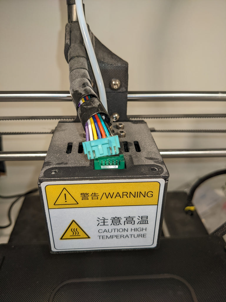
Image 1: loosen the plug connection from the hotend
It is best to check whether you see a fire track here. If this is the case, the wiring harness and the hotend board would have to be replaced here. Especially with Anycubic i3 Mega, It seems to be a well-known vulnerability.
Immediately afterward, open with the loosening of the four Allen screws (the two top front and back at the bottom), the conversion from the hotel, and loosen all cable connections, see Image 2.
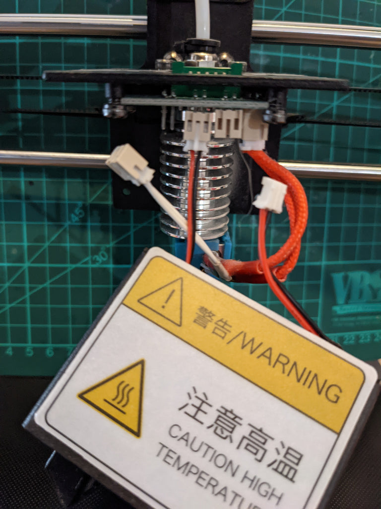
Image 2: Loosen all connections of the hotend board
It is best to remember or photograph the order of the connections so that nothing goes wrong when assembling. Also make sure that the plug for the temperature sensor (white cable) is not kinked too much, otherwise an exchange of the heating cartridge could be necessary.
If all cables are dismantled, loosen the hotend board, which is screwed to the housing via three Allen screws. Now follows the part in which the board must be modified. Knutwurst has provided a nice graphic in his wiki, see Image 3.

Image 3: cabling of the sensor, source Wiki Knutwurst from Github
The version shown was actually too much craft solution, which is why I was very interested in the alternative wiring, see Image 4.
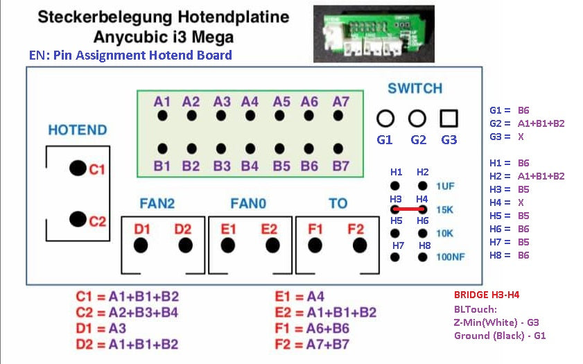
Image 4: Alternative cabling of the sensor, source Wiki Knutwurst from Github
A bridge between H3 and H4 is set on the hotel board, preferably with a 0 ohm SMD resistance so that the connections G1 and G3 are correctly occupied. No matter what variant you prefer, the sensor must ultimately be connected to the B5 and B6 connections.
In my case, the hotel board looks like in Image 5, whereby I chose the alternative variant with 0 ohm SMD resistance.

Figure 5: Finished hot-end board mode
In this case, the pencil strips for our blogs do not fit and I had to push them into the corresponding holes with a little conviction, but with a pliers it was not a problem. Don't forget to solder the two pen strips before installing everything again.
Now an important question that only you can answer! Do you want to use the long line and shorten the plug connection to the hotend board and new criminals, or do you take the short line and have to buy more accessories? To anticipate it right away, I decided on the long line and shortened the connection to the hotend board. The reason is that later when connecting to the 3D printing board, I could faster or replace another sensor. However, this requires that you have the appropriate tool for it! Due to the long line, I also have the advantage that I do not have a fumbling with the plugs on the hotend itself, see Image 6.
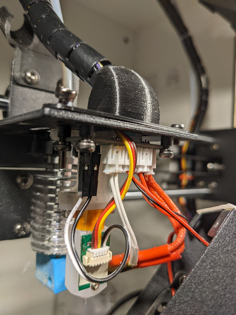
Image 6: Hottend screwed up again and wired
At this point with the pen strips, I used a blob of hot glue for safety, safe. The conductor's wires to the main board of the printer fit between the plug and the housing on the top, see Image 7.

Image 7: Sensor management fits between plugs and housings without any problems
Before you continue, a first test should take place! Be sure to check whether the temperature sensor of the heating cartridges still works, first connect the connector from the hotend, and connect the printer to the cold device plug. After the start of the printer, shows the temperature of the hotend on the display and does not issue any error message, you have installed everything correctly, see Image 8.

Image 8: Hottend shows a temperature of 24 ° C, everything is fine
In the end, everything is now careful again, so that it looks almost like before, see Image 9.

Image 9: Hottend fully assembled again
So that the cable from the 3D Touch V3.0 later does not lie loose in the area and if necessary torn by the movement of the printer, it should be neatly laid into the cable routing. To do this, some cable ties have to be opened so that everything fits cleanly and it ends on the other plugs on the housing, see Image 10.

Image 10: cable led to the printer housing
The conversion and connection on and in the housing
Now it may be shown why I chose this type of connection. The cable fits perfectly to the end of the other plug, only a corresponding connection is missing. Now you could drill an extra hole or carry out an RC service extension between the existing plugs. To do this, you need to open the base plate of the 3D printer and dismantle the connection blank on the side.
Here I mention again that you should separate the printer from the electricity beforehand, as you are now working near 230V!
Loosen the circuit board with the four Allen screws, see Image 11, whereby I recommend solving a few of the plug connections.

Image 11: Board of the three plug connections of the Anycubic i3 Mega S
The other end of the RC servo extension has to go to the printer's main board, to turn the red and brown PIN. Here, for example, simply lift the safety nose of the pins with a safety pin and swap the two veins, see Image 12.

Image 12: The red and brown veins must be rotated
The reason for this is the connection on the main board of the Anycubics, in my case a third-generation trigorilla, see Image 13.

Image 13: RC Servovonation connected to the main board
The original occupancy of the plug is mass (brown), phase (red), and data (yellow). The main board of the Anycubics, on the other hand, needs phase (red), mass (brown), and data (yellow), as can be seen in Image 13 and Image 3. Use the connection with the designation S1 so that you do not have to compile the source code later.
If everything is connected correctly, the plug-in board for the connections on the side can be mounted again and the connection to the 3D Touch V3.0 is established, see Image 14.

Image 14: Servova extension connected to 3D touch V3.0
This also shows the advantage of why I used the long line of the 3D Touch V3.0. Due to the short piece of adapter on the underside of the printer, I save myself from fumbling with the long cable up to about the middle of the cable routing to the hotend. Before you put together the printer completely, you should do a test. To do this, connect the cold device plug to the 3D printer and then switch it on. No matter which firmware runs on your Anycubic 3D printer, the 3D Touch V3.0 should now get the pen and exit and shine red several times, see Image 15.

Image 15: 3D Touch V3.0 lights up red
If he does not do this, please check all plug connections again and whether all connections are correctly connected. Only when the behavior described above shows should you assemble the printer.
New firmware and configuration
Now comes the moment when the printer learns to work with the sensor in the first place. This requires modified firmware for the Anycubic since it cannot do this with the standard firmware. If you have already exchanged the engine drivers, you already know how to update the firmware. Since my printer an Anycubic i3 Mega S is with TMC2208 engine drivers, I need the FW from the Release With the name MEGA_S_TMC_BLT_10_V1.4.3, see Figure 16. The first part is the model, the TMC is the newly built-up driver and BLT is for BL Touch or the leveling sensor, the 10 is for trigorilla subscriptions of the first/third generation and the VX. X.X for the version.

Image 16: Download the correct firmware
How exactly the firmware comes to the 3D printer, I have in the Second part of this series Explained. Take a look at the corresponding chapter again. Restart the printer and select the AutoLeveling entry via the special menu. First of all, the hot end should go to the homeposition immediately after the first measuring point. Immediately afterward, the tip of the 3D Touch V3.0 must extend. Unless this happens, you have to switch off the printer immediately and install the alternative firmware onto the 3D printer. If the desired behavior still does not occur afterward, please check which board is installed and whether you have connected the 3D Touch V3.0 on the S1 connection on the main board. If not, you have to manually build the firmware for yourself, but that blows up the frame here! If everything works so far, the final step follows. The 3D Touch V3.0 is calibrated in the firmware. To do this, you either need a tool like Octoprint or ProntoFace to send and get answers to the printer via terminal commands.
Knutwurst summarized the individual steps very well in 20 points:
- Heat the bed
- G28
- G90
- G1 Z10
- G1 X40 Y40 F4000
- M280 P0 S10
- G91
- With G1 Z-1 or G1 Z-0.1 or G1 Z-0.02 Slower the nozzle until the sensor triggers. NOT FURTHER!
- When the sensor has triggered and flashes: M280 P0 S160
- M114 = Current position of the nozzle -> remember! (e.g. Recv: x: 40.00 Y: 40.00 Z: 1.30 E: 0.00 Count x: 3200 Y: 3200 Z: 520)
- G90
- G1 X38 Y15 F4000 (Values of point 10+offset of the sensor, i.e. x = 40+(-2) and y = 40+(-25)))
- G91
- Place a sheet of paper under the nozzle
- With G1 Z-1 or G1 Z-0.1 or G1 Z-0.02 Slower the nozzle until the paper is difficult to move.
- M114 = Current position of the nozzle -> remember! (e.g. Recv: x: 38.00 Y: 38.00 Z: 0.70 E: 0.00 Count x: 3200 Y: 3200 Z: 520)
- Z -value from point 16 from point 10 pull off -> 1.30 -0.7 = 0.6 mm -> This is our Z-offset.
- M851 Z-0.6 (Attention! Negative signs!)
- M500
- Execute the car over the display again. Complete.
Code 1: Command order for calibration of the sensor
Once you have done all of this, the calibration has been completed and you will probably never have to take care of the right level again. In the special menu, simply select the car leader, don't forget to heat up the heat bed beforehand, and watch the car leap relaxed. As a rule, this does not take longer than 2 minutes.
Conclusion and product rating of the 3D Touch V3.0
Overall, the conversion shown took almost 4 hours. One should not underestimate that soldering skills and, if necessary, also required by Crimea, as well as the necessary tools. Especially with the variant with the 0 ohm SMD resistance you have to work very precisely, so not something for beginners.
The rest is basically simple craftsmanship and should not exactly face a challenge for a maker. However, please make sure that the sensor is connected to the main board that you work on here near 230V! Safety should be in the first place here, so please remove the cold device plug.
What do I personally think of the 3D Touch V3.0? First and foremost, I am more than satisfied with the results after the car level. The print image has improved significantly, even if the new firmware had to perform the complete calibration with PID tuning and extruder calibration. But I would be happy to accept that because a clean first print layer is decisive. The 3D Touch V3.0 is a real alternative to the highly acclaimed BL Touch. It is completely identical in terms of dimensions and connections. So far I haven't used a BL Touch, but with the best will in the world, I cannot imagine that this leveling sensor works so differently. Both retrofit sensors are identical in terms of material and price and I can't say anything bad about the 3D Touch V3.0 in my current attempts. On the contrary, a broken Heatbed doesn't cost me as many nerves anymore as was the case last time because the 3D Touch V3.0 will do the work after the Grundleveling. Trying almost 20 to 25 minutes have become 2 minutes of a car fake! This pays off because from time to time a level of the heat bed makes sense. So can I recommend the 3D Touch V3.0? Here I say yes! Trust the renovation, even if it takes some time, it is worth every single cent. As already written above, I am very satisfied with the renovation and the result and can only recommend it to everyone, provided that no leveling sensor is still installed in the printer. So hit as long as the 3D Touch V3.0 is available in the shop!
This and other projects can be found on GitHub at https://github.com/M3taKn1ght/Blog-Repo.


3 comments
Max
Hallo Jörn,
vielen Dank für die Antwort! Dann passt das alles so, wie ich es habe und das Problem liegt woanders (das Leveling ist nicht so perfekt, wie ich es gerne hätte und ich schließe nach und nach nun die Fehlerquellen aus).
Ich habe nur diesen Teil “durchgearbeitet”, werde mir aber nun auch die anderen zu Gemüte ziehen, da kann ich bestimmt noch etwas lernen.
Viele Grüße,
Max
Jörn Weise
Hallo Max,
dass die Nozzle in der Luft hängt passt. Da du die Differenz zwischen ausgefahrener Spitze vom 3D-Touch und Nozzle bestimmt hast, wird dieser Faktor beim Auto-Leveling mit berücksichtigt.
Beim normalen Drucken sollte die Spitze vom 3D-Touch eingefahren sein, da du sonst die Spitze beschädigen könntest. Grobes Leveling und danach das Autoleveling war genau der richtige Schritt.
Wenn du meine bisherigen Blogs zum 3D-Drucker verfolgt hast, solltest du keiner weiteren Einstellungen machen, andernsfalls musst du im StartCode noch hinterlegen, dass der Drucker seine Default-Parameter aus dem EEPROM lädt.
Wichtig im Startcode ist die folgende Zeile:
M420 S1 ;Use stored Mesh bed leveling
Damit wird die Korrekturmatrix vom Drucker einbezogen und die Nozzle sollte beim Drucken die optimale Höhe haben.
Gruß
Jörn
Max
Nach der Anleitung ging alles gut umzubauen und einzustellen. Nur hängt die Nozzle beim Auto-Leveling-Vorgang in der Luft während der 3D-Touch auslöst. Das so ok ?
Ist der 3D-Touch eingefahren, ist er über der Nozzle. Ausgefahren etwas darunter, das sollte so passen, denke ich. Grobes Leveling per Papier wurde vor dem Auto-Leveling ausgeführt.
Eine andere Frage ist auch noch: muß in Octoprint oder Cura noch etwas eingestellt werden oder läuft das über die Firmware ?