This post is also available as PDF document.
At the Theremin were generated via a PWM output. The ESP32 can do that quite well. However, rectangular singals do not sound intoxicating. They may be difficult for signal tracking in audioclaps. Other signal forms with higher frequencies cannot be created via PWM.
But the ESP32 can do more. After all, there are two DAC channels that convert digital values into analog tensions. That should be enough to create sinus, triangular and sawtooth signals, for example. I describe the way from the first attempt to the finished device
Micropython on the ESP32 and ESP8266
today
The ESP32 tries DDS
DDS is acronym for direct digital synthesis. And in the simplest case, this could be achieved by the fact that individual, consecutive signal levels are calculated in such a way that a certain signal form comes out over time. Of course, these numerical values must be translated into a sequence of voltage values, which is done by a DAC (digital analog converter).
But we want to capture one thing right at the beginning: A real analogue signal will not come out in this way, because the DAC only accepts integers and only in the range from 0 to 255. Accordingly, only 256 different voltage values are possible between 0 and 3.3V. This corresponds to an increase of 3.3V / 256 = 0.0129V as an LSB (Least Significant Bit here: the smallest growth for a counting level). Nevertheless, useful signal shapes can be created, especially if you use a low -pass filter to smooth the steps.
The hardware
|
1 |
ESP32 Dev Kit C V4 unlogged or |
|
Minibreadboard with 400 contacts 3-er set |
|
|
1 |
|
|
1 |
With the exception of the NODEMCU-ESP-32S kit, two Breadboards must be put together on the long sides over two current rails so that the controller has space with all the legs and also remain free slots for the jumper cables.

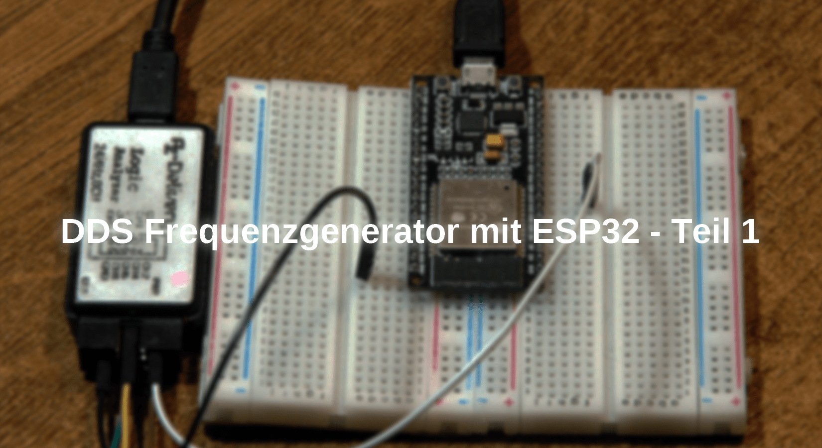
Figure 1: Logic Analyzer on ESP32
I used a Logic Analyzer to measure the frequencies generated. With the free software Logic2 from Saleae you can very precisely determine the period of rectangular signals. The period formation gives the frequency and vice versa from the period.
The software
For flashing and the programming of the ESP32:
Thonny or
Signal tracking:
Used firmware for an ESP32:
The micropython programs for the project:
dac.py First test program
Build_tabbles.py Table generator for the DDSS values
dds_generator.py Demo program with lists of DDSS values
dds_generator_irq.py Operating program
Functionstabellen.py Module with output values for the DAC
Build_tabbles.py Program for creating the functional tables
Micropython - Language - Modules and Programs
To install Thonny you will find detailed instructions here. There is also a description of how the Micropython firmware (as of June 18, 2022) is burned onto the ESP chip. How to get the Raspberry Pi Pico ready for use can be found here.
Micropython is an interpreter language. The main difference to the Arduino IDE, where you always flash entire programs, is that you only have to flash the Micropython firmware once on the ESP32 so that the controller understands micropython instructions. You can use Thonny, µpycraft or ESPTOOL.PY. For Thonny I described the process here.
As soon as the firmware has flashed, you can easily talk to your controller in a dialogue, test individual commands and see the answer immediately without having to compile and transmit an entire program beforehand. That is exactly what bothers me on the Arduino IDE. You simply save an enormous time if you can check simple tests of the syntax and hardware to trying out and refining functions and entire program parts via the command line before knitting a program from it. For this purpose, I always like to create small test programs. As a kind of macro, they summarize recurring commands. Whole applications then develop from such program fragments.
Autostart
If the program is to start autonomously by switching on the controller, copy the program text into a newly created blank tile. Save this file from Main.py in WorkSpace and upload it to the ESP chip. The program starts automatically the next time the reset or switching on.
Test programs
Programs from the current editor window in the Thonny-IDE are started manually via the F5 button. This can be done faster than the mouse click on the start button, or via the Run menu. Only the modules used in the program must be in the flash of the ESP32.
In between, Arduino id again?
Should you later use the controller together with the Arduino IDE, just flash the program in the usual way. However, the ESP32/ESP8266 then forgot that it has ever spoken Micropython. Conversely, any espressif chip that contains a compiled program from the Arduino IDE or AT-Firmware or Lua or ... can be easily provided with the micropython firmware. The process is always as described here.
A first attempt
If only 256 possible voltage values are possible for a period, 256 phase points for a period period of the signal in the event of a saw tooth signal are sufficient that we assign their number to each of the 256 phase points as value. The function sawtooth() does exactly that.
def sawtooth(i):
return i

Figure 2: Development of a saw tooth signal
Similarly, we can create a triangular signal if we increase the output values linearly for the first half of the period and let them fall off linearly in the second half.
def triangle(i):
return i*2 if i <=127 else 511-i*2
A rectangular signal arises if the DAC value is set to 0 and for the rest of the time to 255 for half of the period.
def square(i):
return 0 if i <= 127 else 255
For a sinus course we use the sinus function from the module math. We have to take into account that Micropython uses the arch size for angle sizes. In order to obtain the increment for the angle arguments, we share the full angle 2π (= 360 °) into 256 parts and receive 0.02454. We multiply this value by phase points 0 to 255 and pass on the result to the SIN function, which provides us with values between -1 and 1. We multiply by 127 and lift the zero line to 128.
def sine(i):
return int((128+127*sin(dPhi*i))+0.5) # aufrunden
We are now installing the four functions, the return value of which is the signal level DDSS. As an argument, we hand over the number of the phase.
After the import business, we calculate the angle increment for sinus function. As DAC output, we take GPIO25 that we hand over the constructor of the DAC object.
# dac.py
#
from math import sin, pi
from machine import Pin, DAC
from time import sleep_us
from sys import exit
dPhi=2*pi/255
dacPin=25
dac=DAC(Pin(dacPin))
def sine(i):
return int((128+127*sin(dPhi*i))+0.5)
def square(i):
return 0 if i <= 127 else 255
def sawtooth(i):
return i
def triangle(i):
return i*2 if i <=127 else 511-i*2
while 1:
for phase in range(256): #DDSi = 1
dac.write(square(phase))
The main loop does not have to do anything other than to end without counting the phase numbers and passing it on to the selected function. We send the calculated level value to the DAC converter.
The rectangular signal with a frequency of 143Hz appears on the DSO (digital memory oscilloscope). The Logic Analyzer also provides similar values.

Figure 3: The legal signal brings it to 143 Hz
At the sawtoke, we get 153Hz, at the triangle 136Hz and at the sinus just around 60 Hz. - not exactly intoxicating, we have to work on that. In addition, there is also the defective wave shape of the sine signal, which we cannot leave. The other three signals were ok.

Figure 4: Sinus curve with disorders
The different frequency values first result from the different duration of the signal level calculation in the functions. When calculating the sinus values, the background processes ESP32 with between. If an interruption requirement (IRQ = Interrupt Request) occurs, the ISR (Interrupt Service Routine) interrupts the main program run, which means that the signal level set at this moment is kept longer than beneficial. Apparently around 90ms happens.
The assignment of the signal values to the DAC must therefore go faster in the sinus and, especially for all wave shapes, the same fast. Where is the wand? Hokus - Pokus - we need a solution! And that is: predict the values. In the main loop, they just have to be called up. We produce a set of 256 values per waveform and place it in a list. If we also write the four blocks into a wave shape file, we can import them as a module. Of course, we do not calculate the values ourselves and we do not type in the file. We let the ESP32 do that nicely. We just have to tell him how to do that. Using the example, let's look at how such a value block must look. It is initiated by the definition of a list. Then 8 groups follow with the signal values.
Sinus = [
128, 131, 134, 137, 140, 144, 147, 150,
153, 156, 159, 162, 165, 168, 171, 174,
177, 180, 182, 185, 188, 191, 194, 196,
199, 201, 204, 206, 209, 211, 214, 216,
218, 220, 222, 224, 226, 228, 230, 232,
234, 236, 237, 239, 240, 242, 243, 244,
246, 247, 248, 249, 250, 251, 251, 252,
253, 253, 254, 254, 254, 255, 255, 255,
255, 255, 255, 255, 254, 254, 253, 253,
252, 252, 251, 250, 249, 248, 247, 246,
245, 244, 242, 241, 240, 238, 236, 235,
233, 231, 229, 227, 225, 223, 221, 219,
217, 215, 212, 210, 208, 205, 203, 200,
197, 195, 192, 189, 187, 184, 181, 178,
175, 172, 169, 167, 164, 160, 157, 154,
151, 148, 145, 142, 139, 136, 133, 130,
126, 123, 120, 117, 114, 111, 108, 105,
102, 99, 96, 92, 89, 87, 84, 81,
78, 75, 72, 69, 67, 64, 61, 59,
56, 53, 51, 48, 46, 44, 41, 39,
37, 35, 33, 31, 29, 27, 25, 23,
21, 20, 18, 16, 15, 14, 12, 11,
10, 9, 8, 7, 6, 5, 4, 4,
3, 3, 2, 2, 1, 1, 1, 1,
1, 1, 1, 2, 2, 2, 3, 3,
4, 5, 5, 6, 7, 8, 9, 10,
12, 13, 14, 16, 17, 19, 20, 22,
24, 26, 28, 30, 32, 34, 36, 38,
40, 42, 45, 47, 50, 52, 55, 57,
60, 62, 65, 68, 71, 74, 76, 79,
82, 85, 88, 91, 94, 97, 100, 103,
106, 109, 112, 116, 119, 122, 125, 128,
]
Finally, we close the list bracket.
The program Build_tabbles.py Faring the order for the four wave shapes in about one second. The resulting module Functionstabellen.py is also written in the flash of the controller, so we don't have to put them there.
# build_tables.py
#
# Wertetabellen fuer DDS generieren
#
from math import sin, pi
dPhi=2*pi/255
def sinus(i):
return int((128+127*sin(dPhi*i))+0.5)
def square(i):
return 0 if i <= 127 else 255
def sawtooth(i):
return i
def triangle(i):
return i*2 if i <=127 else 511-i*2
Up to here we already know the matter. Now I create two lists. Functions contain the identifiers of the four functions so that I can automatically refer them in a loop. Functions_text includes the identifiers of the lists to be produced.
The with statement creates a handle f on the file functionstabellen.py for (over) writing. The first of the three for loops runs through the list of function blocks via the index fi. The output takes place via the Handle F and also in Reppl for direct control. First of all, the list definition is written, then we bring the reference to the function in the variable func.
functions=[sinus, square, sawtooth, triangle]
functions_text=["Sinus", "Square", "Sawtooth", "Triangle"]
with open("funktionstabellen.py","w") as f:
for fi in range(len(functions)):
print(functions_text[fi],"= [")
f.write(functions_text[fi]+"= [\n")
func=functions[fi]
for i in range(32):
for j in range(8):
k= i*8 + j
print(func(k),", ",end="")
f.write(str(func(k))+", ")
f.write("\n")
print()
f.write("]\n\n")
print("]\n")
To take 256 values in 8 groups we need 32 lines. We create them through the I-loop. The J-loop Write the individual lines. From I and J we calculate the phase number K, which we are in the function in func() hand over. Back comes an integer that we spend in Repll with a subsequent comma. To ensure that this is done in one line, we give the empty string as a line of lines "" to. For the output in the file, the integer must be converted into a string. A line end must be issued according to the eighth value. We write down in the file New line = "\ n", The function does the function in Repl. print(). At the block end we exclude the list and spend two empty lines as a separator. So that the new file in the flash is displayed in the file list, we click on the three lines (red frame) in Thonny and then on Refresh.

Figure 5: display new file
Then let's see what the action has brought in speed. Instead of calculating the sample values DDSS, we now simply read them from the imported lists, which tightens the scope of the listing. We lay the wave shape to be output by the index Worm in the list Functions_values firmly.
# dds_generator.py
#
from machine import Pin, DAC
from funktionstabellen import *
from time import sleep_us
from sys import exit
#
dac=DAC(Pin(25))
functions_values=[Sinus, Square, Sawtooth, Triangle]
functions_text=["Sinus", "Square", "Sawtooth", "Triangle"]
wForm=0
func=functions_values[wForm]
while 1:
for val in func:
dac.write(val)
In the main loop, only the values now have to be taken from the respective list and output via the DAC. In the case of sinus, the profit of speed is 500%, with the other wave shapes it is also a good 200%. What is not surprising is the fact that the same output frequency is now achieved for all wave shapes, 304Hz. However, there is a light jitter on the DSO in all wave shapes, which is still thanks to the background campaigns of the ESP32, so the frequency still fluctuates by an average. This will not be parked on the ESP32. But we still have a trump card in the hindquarters. After all, the signal form is now for all wave shapes asteep.
The next problem to be solved is the requirement and compliance with a certain frequency. How can we achieve lower and above all higher frequencies with our generator. Now the DDS principle has not yet been fully achieved with the previous programming-why?
We could reach lower frequencies if we incorporated short sleep cycles of the following species into the main loop.
while 1:
for val in func:
dac.write(val)
sleep_us(1)
Each µs increases the lead time of the main loop and thus the period of the output signal increases with an absolute value that is not yet really known. Only measurements of the period duration with the Logic Analyzer or the DSO will help here. I have therefore determined the period for some Sleep values with the Logic Analyzer because it is more precise. We need the steep flanks of the rectangle signal for precise measured values.

Figure 6: Change of frequency through the sleep function - suboptimal!
Without the Sleep command, we have a loop term and thus a peroid time of 3.29ms. Just inserting the Sleep_us statement without delay, Sleep_us (0), brings an extension by 0.87ms. But even with the step from 0µs to 1µs, the period duration does not increase by expected 256µs but by 31µs. This value increases up to 258µs / µs and is only relatively constant at 20µs. The frequency change happens, especially at the beginning, in large jumps - so that is not a solution. But it is still not really DDS.
After all, we already come to about 300Hz with a period of 3.29ms. The next approach is approaching DDS and uses a hardware timer of the ESP32 to output the 256 signal values of the table. The timing is fixed and should make calculations reliable. But how can we get variable frequencies with a fixed timing?
The frequency would be better adjustable if we had more phase levels. How about 65536 or 1677216? Then we also need as many signal values in the lists, do you think? Not necessarily! Let's stay with values from 0 to 65535 = 0xffff. We can now increase the DDSP value by any increment DDSD from this range of values. This means that we reach the maximum value 0xffff or exceed it more or less quickly. Then the count automatically begins again. If we only add a small increment, then we hesitate the overflow of the phase pointer that sinks frequency.
If we now use the MSB (MOST Significant byte = higher valuable byte) of the phase pointer as an index in the table of signal values, we can change the frequency in small stages without needing more than 256 signal values.

Figure 7: Scheme of a DDS system
We learn how the time sequence of the main program and ISR (Interrupt Service Routine) of the timer is through a trick from the program itself. The main loop is now actually unemployed. She only has the PIN loop= PIN (12) to switch on and off constantly. Channel 1 of the DSO shows us when the Main Loop is active. When entering the timer() let's leave the PIN IRQ= Switch on the pin (12) and switch off again after the work is done (channel 2). While the ISR has command, switching the main loop is silent. That looks like this.

Figure 8: IRQ-Timing
We recognize the following time of the Timer interrupt of 1MS very well. In between there are countless impulses from the main loop. Let us take a closer look at the environment of an interrupt.

Figure 9: IRQ-Timing Detail
After the last flank of the main loop clock, 18.4µs pass until the ISR reports to the rising flank. The ISR operations need 45.8µs. Only 16µs after the end of the ISR does the beat of the main loop set up again. An IRQ event therefore takes a total of approx. 70µs. If we have an IRQ sequence of 80µs
(with buffer to 70µs), we would get a output frequency of our DDS signals from just 48Hz. The output signal of the present arrangement is due to the long IRQ sequence times of 1ms at less than 4Hz-yes, four Hertz! Operative panting - then was that all for the cat? Yes - Probably with the ESP32 alone. But There must be a solution, otherwise I would not have written this article.
There are even two solutions. We could buy a DDS chip or program yourself. I chose the latter because it is more cost -effective and, above all, an electronics engineer more exciting and interesting. We have just developed the basics of DDS. What we need is a drastic increase in speed. The realization that the ESP32 is not directly suitable for this purpose using micropython is by no means leading the project. A division of labor is targeted. The ESP32 will get the control roller and another microcontroller will create the signals. So what's next?
What we need is a microcontroller that can be programmed under assembler -close. We achieve two improvements:
- Assembler is a programming -related programming and provides very fast programs. By selecting the commands and structures used, the program can be optimized for speed.
- We only decide who interrupts the CPU when. This gives us perfect signal curves.
I rummaged in the handicraft box and found an Atmel Attiny2313. Although it is only clocked at 16 or a maximum of 20 MHz, it delivers DDS signals up to 20kHz and that can be revealed, in addition to the program itself, it also has space for up to 6 wave shapes, despite the only 2 KB program memory.
The program is written in AVR assemblers. The free Atmel studio 7.0 will help us. With the also free AVRDUDE tool, we will quarter the program on the Tiny 2313. As a programmer, I have an MK II from ATMEL. But you can easily set up an Arduino lying around for this purpose.
We will deal with these topics in the next episodes. So stay tuned!


1 comment
Harry
Man könnte natürlich das Ganze auch auf dem ESP32 in C bzw. C++ programmieren. Dann spart man sich den zweiten (ATMEL)Prozessor.