This blog sequence is also available as a PDF document.
Many people plan to plant their garden or balcony early on. You can buy the plants for it or use it yourself. But what to do if you are not at home for a week? Who pours the plants and snuggles when it gets fresh on the windowsill at night? And when it gets dark, who makes light in the best spectral composition? The answers and various tips for Micropython are available in the new series of
Micropython on the ESP32 and ESP8266
today
Part 1 - Small climate Test with the AHT10
I have had to do with the difficulties mentioned above in recent years. That's why I decided to build an assistant for the cultivation and care of my seedlings this year. The small climate in the seed box will monitor an AHT10, the programming of which I will introduce to you in this blog sequence. Further contributions to the individual assemblies will follow.
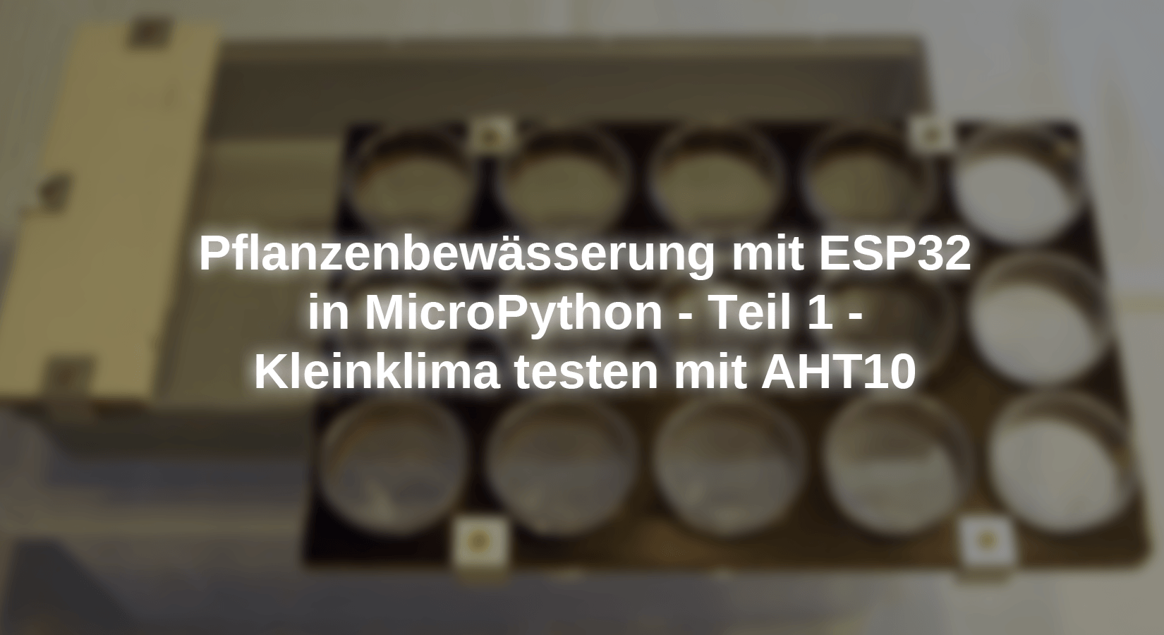
As a home for the seedlings, I got a transparent box from the hardware store. There fits a bowl that is actually intended for cutlery parts. I covered them with a waterproof tumbled plywood plate, in which I drilled 15 holes 4cm in diameter. It serves as a holder for the stable, reusable plastic schnapps glasses from the supermarket, the floors of which I have provided with some holes so that the plants that are supposed to live there can also absorb water from the bowl.

Image 1: Water bowl with use

Image 2: Square for 15 breeding cups and the climate of goods
In the following articles, I will shed light on the various stations for the implementation of the project. Hardware and software are modularly kept so that you each treat a specific topic. However, the modules are independent. This gives you the option of selecting the parts you want to implement personally. Let's start today to find out the small climate in the seed box that through the sizes temperature and relative humidity is determined. The AHT10 can measure both and transmit the I2C bus to the controller, an ESP32.
Hardware
As a controller, I chose an ESP32 because it can come up with sufficiently freely selectable GPIO connections. We need 10 pieces of it when fully removed.
The ESP32 models in the partial list are all useful. Only the ESP32-Lolin-Board must be used for the I2C connection SDA instead of GPIO21 of the GPIO25 PIN.
|
1 |
ESP32 Dev Kit C V4 unplacerated or |
|
1 |
|
|
1 |
|
|
1 |
|
|
|
Jumper Wire cable 3 x 40 pcs. 20 cm M2M / F2M / F2F each possibly too |
The software
For flashing and the programming of the ESP32:
Thonny or
Used firmware for the ESP32:
The Micropython programs for the project:
SSD1306.PY Hardware driver for the OLED display
oled.py API for the OLED display
aht10.py API for the temperature moisture module
temphum.py Demo program
Micropython - Language - Modules and Programs
To install Thonny you will find one here Detailed instructions (English version). There is also a description of how the Micropython firmware (As of 18.06.2022) on the ESP chip burned becomes.
Micropython is an interpreter language. The main difference to the Arduino IDE, where you always flash entire programs, is that you only have to flash the Micropython firmware once on the ESP32 so that the controller understands Micropython instructions. You can use Thonny, µpycraft, or ESPTOOL.PY. For Thonny I have the process here described.
As soon as the firmware has flashed, you can easily talk to your controller in a dialogue, test individual commands and see the answer immediately without having to compile and transmit an entire program beforehand. That is exactly what bothers me about the Arduino IDE. You simply save an enormous time if you can check simple tests of the syntax and hardware to try out and refine functions and entire program parts via the command line before knitting a program from it. For this purpose, I always like to create small test programs. As a kind of macro, they summarize recurring commands. Whole applications then develop from such program fragments.
Autostart
If the program is to start autonomously by switching on the controller, copy the program text into a newly created blank tile. Save this file under boot.py in WorkSpace and upload it to the ESP chip. The program starts automatically the next time the reset or switching is on.
Test programs
Programs from the current editor window in the Thonny-IDE are started manually via the F5 button. This can be done faster than the mouse click on the start button, or via the menu run. Only the modules used in the program must be in the flash of the ESP32.
In between, Arduino id again?
Should you later use the controller together with the Arduino IDE, just flash the program in the usual way. However, the ESP32/ESP8266 then forgot that it has ever spoken Micropython. Conversely, any espressif chip that contains a compiled program from the Arduino IDE or AT-Firmware or Lua or ... can be easily provided with the micropython firmware. The process is always like here described.
Circuit and structure
Our circuit is very clear, it only contains the ESP32, an AHT10 and a 3-line OLED display.

Image 3: AHT10 am ESP32
The structure takes place on two breadboards stuck together along one another with a central power rail. The arrangement offers enough space for future extensions of the project.

Image 4: AHT10 with ESP32 - parts arrangement
We will try a few things shortly, so it is good if you ever plug in the circuit.
AHT10 versus DHT11, DHT22
What is the difference between ATH10 and the DHT brothers? The connection to a microcontroller is very crucial. The DHTS (except DHT20) need their own GPIO PIN per piece, because they have no address like an I2C component, for example, the AHT10. Of course, no other device can be connected to a DHT GPIO.
I2C is an acronym for an inter-integrated circuit. This bus was introduced by Philips to network different assemblies in one device. Bus means that several building blocks are connected to each other via the cables SDA and SCL (Serial Data and Serial Clock) and are addressed via a so-called hardware address at the beginning of contact.
This procedure enables us to be supplied with the same GPIO pins. Unfortunately, the hardware address of both modules cannot be changed, so that only one copy of each variety can be on the bus.
Other I2C modules that can also measure temperature and relative air humidity are the SHT21 or the BME280. The BME280 will be in one of the next blog posts of the Star of the County Down. I already have the use of the SHT21 in the blog sequence for the Mammut matrix display presented. There were problems with such a building block that, as it turned out, had a corrupt inner life.
Of course, there are other differences in addition to the interface, some of which I have put together in Table 1.
|
Characteristic |
DHT11 |
DHT22 |
AHT10 |
HTU21 |
BME280 |
|
Temperature range |
0..80 ° C |
-40..100 ° C |
0..100 ° C |
40..125 ° C |
-40..85 ° C |
|
resolution |
1 ° C |
0.1 ° C |
0.01 ° C |
0.01 ° C |
k. A. |
|
Reln wet |
0..80% |
0..100% |
0..100% |
0..100% |
0..100% |
|
resolution |
1% |
0,1% |
0,024% |
0,04% |
0,008% |
|
Price |
* |
* .. ** |
* |
* |
*** |
|
I2C |
- |
- |
Yes |
Yes |
Yes |
|
Complexity of micropython programming according to the data sheet |
* |
* |
** |
** |
**** |
Table 1: Building block comparison
Signals on the I2C bus
Whenever there are problems with data transmission, I like to use the DSO (digital memory oscilloscope), or a smaller tool, which is cheaper to the world, one Logic analyzer (La) with 8 channels. The thing is connected to the USB bus and shows by means of Free software what is going on on the bus pipes. Where the shape of impulses does not matter, but only on its time sequence, a LA is worth gold. While the DSO only provides snapshots of the curve, you can feel the LA over a long time and then zoom yourself into the interesting places. You can find a description of the device in the blog post "Logic Analyzer Part 1: Make I2C signals visible"by Bernd Albrecht. There is also described
How to scan the I2C bus.

Image 5: Logic Analyzer on the I2C bus
I will present the transfer of the hardware address (HWADR) to the AHT10 followed by a data byte. To do this, I put PIN 1 of the Logic Analyzer on the SCL line and PIN 2 of the Logic Analyzer with a jumper cable to the SDA line of the I2C bus. I connect to GND.
Now I start Thonny, create a new file in the editor and enter the following text.
From machine import Pin code,Softi2c
import sys
IF sys.platform == "ESP8266":
I2C=Softi2c(scl=Pin code(5),sda=Pin code(4))
elif sys.platform == "ESP32":
I2C=Softi2c(scl=Pin code(22),sda=Pin code(21))
Else:
raise Runtime("Unknown Port")
The variable sys.platform Tell us which controller type we use. An I2C object is instantiated on this, which we will use for the first test. Is the ESP32 and its circuit ready and is the controller connected to the PC? Then we start the program with the F5 button. This is faster than using the green start button with the white triangle. If the program runs through without an error message, everything is ok. In the terminal, we now enter the first I2C command and want to see who is there. I format input, the answers from the system in italics.
>>> I2C.scan()
[56, 60]
The square brackets in Micropython have a so-called list it contains the 7-bit hardware addresses of the I2C modules found as elements. 56 = 0x38 The number is to which the AHT10 reacts, 60 = 0x3c must therefore be the OLED display. The bus is ready and is waiting for the communication of the ESP32 with the connected parties.
In order for the bush drum to work, there must be one that indicates the clock. This is the ESP32. He is the boss and that means at i2c master. The AHT10 and the OLED display are the slaves, the slaves. - Ohhh! I thought the age of slavery was long gone! - be it, the master indicates the slave with which he wants to paralyze. He also creates one Start Condition As a kind of "respect for all" message. Then he puts the hardware address on the bus to which he as LSB (Least Significant Bit) attaches a 0 if he wants to send data (write) or 1 if he expects the slave an answer (read). The hardware address follows the data byte to be sent in the event of writing access. Finally comes a "ok, that's it", Stop Condition. We take a look at what the signal sequence looks like.
I enter the following command in the terminal area of Thonny but don't send it off yet. The Logic Analyzer is connected as described above.
>>> I2C.writeto(0x38,B "\ XBA")
Next, I start the program Logic 2. In the menu on the right side of the window, I click on Analyzers And then on the plus sign. I choose from the list I2C.
Now everything is prepared, we start the recording with the R button and quickly switch to Thonny, and press the Enter key to send the command. Then quickly back to Logic 2 and stop the recording with R.

Image 6: Logic Analyzer on the I2C bus
To see the entire signal sequence, I put the mouse pointer on one of the signal tracks and turn the mouse wheel to me. At some point, a vertical line appears in the recording tracks. Then I put the mouse pointer on this line and turn the mouse wheel away from me. The line is getting wider and wider until I can see the signal pulses. I have marked the most important places with time brands.

Image 7: Soft reset of the AHT10
The brand 0 marks the Start Condition, Sda goes to low while SCL is high. Then the master waits about 15µs so that the slaves come from the springs to receive them at a hardware address. We have given 0x38 = 0b00111000. The ESP32 turns this to the Bits 0B011100 and attaches a 0 as an LSB because it wants to send the AHT10 a byte. Then he puts the address byte on the bus. With every rising flank (e.g. brand 1 and 2) of his clock signal on SCL, he tells the slaves that they should now remember the condition of the SDA line. The master sent the Byte 0x70 = 0B01110000. With the Acknowledge-Bit (ACK), the slave on the ninth rising flank signals whether he received the byte from the master and recognized it as his address. In this case, like here the AHT10, he pulls the SDA line to 0. The other slaves on the bus pull their sleeping caps over their ears and whip. In the same way, the Master will send the byte 0xBA next, which the AHT10 acknowledges again with a field. Then the slave releases the SDA line again. The master does not create a new clock pulse, SCL remains on 1. If the master now also releases the SDA line, released lines go through the pullup resistances on high levels, this is the Stop Condition.
The I2C routines of the Micropython module work according to this scheme AHT10.py. Before we take a closer look, I have to point out a microphone-specific thing. Micropython knows no type declarations for variables as are common in C. Nevertheless, there are a few simple data types that Micropython sometimes treats transparently without grumbling.
>>> A="123"
>>> A
'123'
>>> A=123
>>> A
123
The second instruction Flight becomes an integer number. But while in Lua Node-McU or Perl the following line results in the value 246,
>>> A+"123"
246
We receive an error message in Micropython because Micropython does not know any implicit types of types.
>>> A+"123"
Traceback (custody recent call load):
File "" , line 1, in <modules>
Type: can'T Convert'intimately'Object to Str Implicitly
Micropython copes with an explicit type conversion:
>>> A+intimately("123")
246
In the case of the i2C statement
>>> I2C.writeto(0x38,B "\ XBA")
Expects Micropython as a hardware address. Instead of 0x38, we could also use 56 (decimal). As a data-byte (-s), the method expects writeto() But a data type that supports the buffer protocol, but does not do the number of integers, nor do strings. Therefore, you have to hand over the data either as a bytes object, as I did here, or as a bytearar. That would look like this:
>>> buf=bytearar(6)
>>> buf[0] = 0xba
>>> I2C.writeto(0x38,buf[0:1])
>>> buf[0]
186
>>> buf[0:1]
bytearar(B '\ XBA')
BUF is a bytearar and this supports the buffer protocol. While buf[0] The integer value 0xBA represents that does not. So I am not allowed buf[0] handed over but the part (slice = disc) of buf take that contains only the first element, buf[0:1].
After this atmosphere, we are now coming to class AHT10 in the Micropython module AHT10.py is declared.
The module for the AHT10
# aht10.py
From time import Sleep_ms
From sys import exit
From math import log
Some methods of the class AHT10 have to keep waiting times until the AHT10 chip has carried out the received order and provided the data. For this, we import the function Sleep_ms() from the module time. We need the function to calculate the taupunkt logthat can calculate the logarithm of naturalis. It is in the module math.
The declaration of the class follows AHT10.
class AHT10:
    Hwad   = const(0x38)

    Initcmd = (0xe1, 0x08, 0x00)
    Triggercmd = (0xac, 0x33, 0x00)
    Softrstcmd = const(0xba)
    Bussy = const(0x80)
    Calibrated = const(0x08)
    DENOMINATOR = const(2**20)
    K2 = 17.62
    K3 = 243.12
The function of the AHT10 is controlled in an unusual way. No registers are addressed, but commands are sent. For the initialization and the triggering of measurement, three bytes are transferred as a command for the soft reset we have already met only one. In the case of a reading command, the AHT10 always transmits six bytes, the first is the status byte, and the following five contain temperature and moisture raw values.
As long as that Busy-Flag (MSB in the status byte) is to 1, the AHT10 still has to do and the ESP32 must wait. In addition, the measurement only works if that calibrated-Flag is set in the AHT10. This is done by initialization. Unfortunately, the datasheet does not provide the comprehensive information that is expected of a programmer. A part is also interspersed with Far Eastern Hieroglyphs, the importance of which you have to find out through experiments. That cost a lot of time here and only brought something occasionally.
To calculate the true measured values, you need a divider of 2 high 20, which I put into the constant denominator. K2 and K3 are constants that are used using the Magnus formula needs to make temperature and rel. Air humidity to be able to calculate the dew point temperature.
    def __init__ (self, I2C):
        self.I2C=I2C
        Sleep_ms(20)
        self.buf=bytearar(6)
        self.reset()
        self.tempo= 9999
        self.humble = 9999
        print("AHT10 ready")
        try:
            self.Begin()
        except:
            print("Device error")
            sys.exit()
The constructor of the class must only be handed over to an I2C object in the instantiation, which must be generated in the calling program. It takes a start time of 20ms until the AHT 10 can be painted.
A bytearar of length 6 is declared, with which we will later handle I2C traffic. By default, there is a soft reset. Provides initialization by the method Begin() True Back, then the AHT10 is ready for use, otherwise, we will receive an error message and the program stops.
    def reset(self):
        self.buf[0]=Softrstcmd
        self.I2C.writeto(Hwad,self.buf[0:1])
        Sleep_ms(20)
The soft reset is in the manner already described above with the global bytearar buf completed. Then again, like at the start, 20ms rest.
    def Begin(self):
        for I in range(0,3):
            self.buf[I]=AHT10.Initcmd[I]
        self.I2C.writeto(Hwad,self.buf[0:3])
        self.WAITRDY()
        IF need(self.status() & Calibrated):
            raise Runtime ("AHT10 not initial")
We fill the bytearar buf With the three bytes of the initialization command Initcmd in the for loop, in order to send the disc with the first three elements of the array to the AHT10. Keep in mind that Micropython sequential data types from 0 indicate that the last element has an index that is 1 smaller than the specified upper limit. [0: 3] therefore addresses the elements 0.1 and 2 as a sub-area (slice) of the array buf. We are waiting for the Bussy flag 0 to be becoming and checking the Calibrated flag Fierce With the mask. If it is set, the expression has the value 16 and is a True classified. Otherwise, 0 comes out what you do False is equivalent to. One Runtime-Exception Throwing is another way to provoke a program if the exception is not intercepted by the calling program.
    def WAITRDY(self):
        S=self.status()
        while S & Bussy:
            Sleep_ms(2)
            S=self.status()
WAITRDY() calls the status of the AHT10 by calling the method status() away. The While loop is only left when the expression Status-byte & bussy a 0 delivers.
    def status(self):
        self.read sensor() # First byte is status byte
        return self.buf[0]
status() leaves over read sensor() The 6 bytes from the sensor to the bytearar buf Lead and only give the numerical value of the first array element, buf[0], back.
    def read sensor(self):
        self.I2C.readfrom_into(self.Hwad, self.buf)
read sensor() Forms the lowest hierarchy level when reading. I2C.Readfrom_into() reads as many bytes from the AHT10 as in the bytearar buf fit and that are 6 pieces.
    def triggerDevice(self):
        for I in range(0,3):
            self.buf[I]=AHT10.Triggercmd[I]
        self.I2C.writeto(Hwad,self.buf[0:3])
Every new measurement has to be triggered, there is no freewheel mode. triggerDevice() is known to send the three commandobytes of Triggercmd.
    def getvalues(self):
        self.WAITRDY()
        self.read sensor()
getvalues() Waits the end of the measurement process and then lets the values read in. This method is actually superfluous because the latter has yes WAITRDY() ready that in turn does nothing other than continuously the AHT10 using read sensor() to querge. The attribute buf is global in the AHT10 class and therefore accessible from anywhere within AHT10 at every level. WAITRDY() will be left when the Bussy flag is 0. Then the measured values are already in the elements 1..5 of the bytearar buf contain. But it would be mystical and difficult to understand if only after one WAITRDY() the user data would already be calculated from the raw data. We treat ourselves to these three lines because of clarity.
    def gettem temp(self):
         self.getvalues()
         raw = ((self.buf[3] & 0xf) << 16) | \
               (self.buf[4] << 8) | self.buf[5]
         return raw * 200 / DENOMINATOR - 50
Cells 3.4 and 5 of buf contain the temperature raw value. In fact, only the lower 4 bits of buf[3], the low-nibble, to attribute the temperature. But they form the four high-quality bits of the intermediate value raw. Because 16-bit positions are below, I insulate the low-nibble from buf[3] through Fierce With 0x0f and push the bits 16 places to the left. The next 8 bits deliver buf[4], I push them to the left by 8 positions and or ores this with the previous value. The lowest 8 bits can then be buf[5] to be filled by Oder.
The following presentation may better convey the process:
Let us assume, Buf [3: 6] has the form (0b ???? xxxx, 0byyyyyyyy, 0Bzzzzzzzzz), then the following happens, although?, X, Y, and Z represent bit positions.
0b ???? XXXX& 0B00001111
= 0b0000xxxx
0b0000xxxx << 16
0bxxxx 00000000 00000000
0byyyyyyy << 8
0byyyyyyy 00000000
0bxxxx 00000000 00000000
| 0byyyyyyy 00000000
| 0 bizzzzzzz
= 0bxxxx yyyyyyy zzzzzzzzz
According to the datasheet, this 20-digit binary number must now be multiplied by 200 and divided by 2 high 20. If 50 is then removed, you get the temperature in degrees Celsius. This is exactly what happens in gettem temp().
    def gefhum(self):
        self.getvalues()
        raw=(self.buf[1] << 12) | (self.buf[2] << 4) | \
             (self.buf[3] >> 4)
        return raw * 100 / DENOMINATOR
Works similarly gefhum(), only here are the upper four bits of buf[3] The lowest quality nibble of the raw value. Pushing the bits there by 4 positions to the right. buf[1] and buf[2] Jumps by 12 or 4 positions by pushing left. Again a 20-digit binary number is created, but now only to multiply by 100 and by the constant denominator = 220 It is to be divided to obtain the value of the relative humidity.
    def Getdewpoint(self):
        tempo=self.gettem temp()
        humble=self.gefhum()
        DP= AHT10.K3 * ((AHT10.K2 * tempo)/ \
                        (AHT10.K3 + tempo) + log (humble/100))/\
                       ((AHT10.K2 * AHT10.K3) /  \
                        (AHT10.K3 + tempo) - log (humble/100))
        return DP
The dew point is the temperature at which the invisible water vapor in the air begins to condense. Then fog forms, slices fogged. I used the formula (15) on the specified Wikipedia page to calculate the dew point after reading the temperature and moisture values.

Image 8: Dew point calculation according to Magnus
Please remember to call gettem temp(), gefhum() and Getdewpoint() trigger a measurement, triggerDevice(). Temperature, moisture and dew point are then calculated from the same data record. The demo program temphum.py shows the application of the class. The discussion follows after the listing.
# temphum.py
From AHT10 import AHT10
From machine import Pin code,Softi2c
import sys
From time import sleep#, ticks_ms
From OLED import OLED
IF sys.platform == "ESP8266": # (1)
I2C=Softi2c(scl=Pin code(5),sda=Pin code(4))
elif sys.platform == "ESP32":
I2C=Softi2c(scl=Pin code(22),sda=Pin code(21))
Else:
raise Runtime("Unknown Port")
D=OLED(I2C,Heightw=32) # (2)
D.writer("Hygro-Therm",2,0)
sleep(3)
AHT=AHT10(I2C) # (3)
TPIN=0
button=Pin code(TPIN,Pin code.IN,Pin code.Pull_up)
while 1: # (4)
AHT.triggerDevice()
D.clearall(False)
tempo=AHT.gettem temp()
humble=AHT.gefhum()
DP=AHT.Getdewpoint()
# (5)
print("Temp: {: 0.2f}; Hum: {: 0.2f}; dp: {: 0.2f}".\
format(tempo,humble,DP))
# (6)
D.writer("Temp: {:> 6.2f} *C".format(tempo),0,0,False)
D.writer("Hum: {:> 6.2f} %".format(humble),0,1,False)
# (7)
D.writer("DP: {:> 6.2f} *c".format(DP),0,2)
sleep (1)
IF button.value() == 0: # (8)
D.clearall()
D.writer("Program Canceled",0,0)
sys.exit()
Before we from the module AHT10 the class AHT10, the file must be imported AHT10.py are uploaded to the flash of the ESP32. Right-click on the file and Upload to /.

Image 9: Upload module
From the machine, we need a Pin code and Softi2c. PIN for declaring the GPIOs for Scl and Sda as well as the button. Softi2c I like to use it because I can then choose the connections for the bus freely.
sys provides us with the text constant platform and the function exit(). This gives us access to the controller type - "ESP32" or "ESP8266" - and the opportunity to leave the program in an orderly.
With sleep() from the module time Let's send the ESP32 for the number of seconds to snore. The argument may also be of the type float And also be smaller than 1.
The class OLED offers us a comfortable API for the control of the OLED display. Later more.
@ (1)
The IF construction allows me to work across platforms without any changes to the program. Each type of controller chooses the right pins for the I2C bus. Other port-dependent declarations could also be installed here, for example for ADC or PWM objects.
@ (2)
The constructor of the OLED class needs for the position parameter I2C The just declared I2C instance and the display height Heightw = 32. The optional parameter has the default value 64, the default width is width = 128. It does not have to be specified because the value corresponds to our display. We have the application title displayed for three seconds.
@ (3)
We instantiate that AHT10-Object AHT And the GPIO object button. As hardware, we use the flash button of the ESP32 on GPIO0. The connection already has an external pullup. Nevertheless, I also switch on the internal, because if another GPIO PIN is ever chosen, then I no longer need to make a change in the declaration. I only change the assignment TPIN. Use here and with (1) as with the text modules of a text processing program - once defined.
@ (4)
The While loop is the main loop and runs endlessly as long as the ESP32 juice has and the flash button is not pressed.
We trigger a measurement. While the AHT10 works, we delete the display. Because of the argument False that happens in the background. This means that only the buffer memory in the RAM of the ESP32 with zeros is described. However, the content is not yet sent to the display module, which still shows the title at this point.
Then we pick up the values. If the AHT10 is not yet finished with the measurement, the waiting for it in the background and transparently the method for us AHT10.Getvalues() that from gettem temp(), gefhum(), and Detdp() is called.
@ (5)
The print command uses formatting instructions to specifically mix text and numerical values, here of the Float type. The number format is given in curly brackets. According to the colon, the value stands for the minimum width of the number to be output. The zero is the default value and could also be omitted without changing the output. The information is ignored anyway when the number, including separation signs, has more places than the minimum width indicates. With the point and the following number, the number of decimal places is set for floating point numbers, here 2. The F specifies the type of number.
@ (6)
The values on the display should be decimal point under decimal point. Because no value with a sign can be wider than 6 places, I enter as a minimum width 6 and make sure with the ">" that the formatting is right. This procedure quasi replaces a right or decimal tab.
@ (7)
Only this writing command sends the content of the drawing buffer to the OLED display. This procedure prevents the display from flickering. Try what happens when False left out of the writing instructions in the loop, or through the optional True be replaced.
@ (8)
If the flash button is pressed when the program arrives at the IF construction, the display is deleted and the text "Program Canceled" is output. Then ended exit() the program execution.
We arrived at the end of the climate part. The AHT10 can now provide the ESP32 the information whether the small climate in the seed box fits, whether heated or cooled and whether the humidity fits for growth.
In the next episode we will bring light into the matter, it will be about lighting the plantation. You can go in search of a strong 5V power supply. Together with the heating and the pump, we come to 3.5 to 4 amps in the final expansion if all three main consumers are activated at the same time.


7 comments
Ralf Eisele
Hallo Jürgen,
vorerst letzter Komentar.
Habe jetzt alle i2c Komponenten an einem RasPI 3B getestet, alle funktionieren auser die AHT10, alle drei von AZ defekt. der AHT21 wird vom PI erkannt aber nicht vom ESP.
Sobald es was positives gibt werde ich mich nochmal melden.
Grüße
Ralf
Ralf Eisele
Hallo Jürgen, danke für deine Antwort.
Wollte dir noch Rückmeldung geben.
Habe alle erdenklichen Kombinationen durchgespielt,
Mit den verschiedenen I2C Sensoren und IC’s. Es wird grundsätzlich nur das OLED derkannt.
Keine anderes Modul wird erkannt, werde jetzt mal einen anderen ESP32 testen, möglicherweise hat auch der Bus ein Problem.
Werde auf jeden Fall nochmal Rückmeldung geben, schon seltsam.
Grüße
Ralf
Jürgen
Hallo, Ralf,
in meiner Antwort an Ernst Barenschee habe ich schon einige Möglichkeiten zur Fehlerbehebung aufgeführt. Seltsam ist in deinem Fall, dass das OLED offenbar anspricht und der AHT10 nicht. Die Anschlüsse meines Moduls, das zusammen mit einem OLED einwandfrei funktioniert, sind :
Vcc
GND
SCL
SDA
Es ist zwar unwahrscheinlich, aber nicht auszuschließen, dass die Anschlüsse deines Moduls von denen im Schaltplan abweichen.
Folgendes Testprogrämmchen könntest du mal verwenden, um den Fehler einzugrenzen:
AHT10-test.pyfrom aht10 import AHT10
from machine import Pin,SoftI2C
from oled import OLED
i2c=SoftI2C(Pin(22),Pin(21),freq=100000)
d=OLED
aht=AHT10
Und das sollte dabei herauskommen:
>>> %Run -c $EDITOR_CONTENT
this is the constructor of OLED class
Size:128×64
AHT10 bereit
>>> i2c.scan()
[56, 60]
Du könntest auch mal das OLED entfernen und testen, ob der AHT10 dann anspricht. Das wäre die Umsetzung des Vorschlags von Ernst Barenschee.
AHT10-test.pyfrom aht10 import AHT10
from machine import Pin,SoftI2C from oled import OLED
i2c=SoftI2C(Pin(22),Pin(21),freq=100000)
d=OLEDaht=AHT10
>>> %Run -c $EDITOR_CONTENT
AHT10 bereit
Ralf Eisele
Guten Morgen,
bei mir kommt die Meldung
OLED API OK
Size:128×32
Traceback (most recent call last):
File “”, line 19, in
File “aht10.py”, line 22, in init
File “aht10.py”, line 34, in reset
OSError: [Errno 19] ENODEV
Viele Grüße und Danke
Ralf
Ernst Barenschee
Das Problem lässt sich lösen, wenn man den AHT10 Sensor durch einen AHT21 ersetzt. Die MicroPhyton Bibliothek funktioniert für beide Sensoren gleich. Der AHT21 kann einfach als drop-in verwendet werden, ohne weitere Änderungen. Damit läuft das System stabil. Ich vermute, dass es mit dem AHT10 an der I2S Schnittstelle Probleme gibt, sobald dort ein weiteres Gerät (hier das Oled Display) angeschlossen ist. Der AHT10 Sensor funktioniert einwandfrei mit einem Arduino nano, ohne weiteres Gerät an der I2S Schnittstelle.
Jürgen
Herr Barenschee, der Beitrag wurde im Januar 2022 verfasst. Offenbar hat MicroPython wieder einmal, wie bereits eineige Male in der Vergangenheit die Links zur Firmware geändert. Der korrekte Link lautet jetzt (Sept. 2023) :
https://micropython.org/resources/firmware/ESP32_GENERIC-20220618-v1.19.1.bin
Ihr Problem kann ich an meinem Aufbau nicht nachvollziehen. Die Schaltung lief im Einsatz prblemlos über mehrere Wochen. Ich hab sie grade wieder ausgegraben und noch einmal in Betrieb genommen. Auch jetzt kann ich kein Problem orten.
Seltsam ist, dass das Programm eine Zeit lang läuft und erst nach mehreren Durchläufen streikt. In jedem Fall ist es wohl ein I2C-Problem. Käme die Meldung ENODEV gleich beim Start, läge es vielleicht an vertauschten SCL- SDA-Leitungen, einer fehlerhaften Vcc- oder GND-Leitung. Ist Ihre Schaltung vielleicht berührungsempfindlich? Taucht der Fehler auch auf, wenn Sie den Aufbau nicht berühren? Es könnte ein Wackler an einem Kontakt oder ein Kabelbruch sein, der die Kommunikation stört. Interessant könnte in Ihrem Fall die Aufzeichnung der I2C-Signale mit dem Logic Analyzer sein. Tauschen Sie evtl. die Kabel am Bus und an der Versorgung aus.
ENODEV deutet darauf hin, dass nach dem Senden der Geräteadresse durch den Controller vom Slave kein ACK-Bit kommt. Versuchen Sie doch einmal nach so einem Absturz den I2C-Bus zu scannen.
>>> i2c.scan()
Die Antwort sollte [56, 60] sein, wenn die Bausteine korrekt ansprechbar sind.
Welche Parameter weist die I2C-Instanz auf?
>>> i2c
SoftI2C(scl=22, sda=21, freq=500000)
Versuchen Sie auch, die Übrtragungsrate zu senken.
>>> i2c=SoftI2C(scl=Pin(22),sda=Pin(21),freq=100000)
>>> i2c
SoftI2C(scl=22, sda=21, freq=100000)
Abschließend, haben sie schon einmal die Versorgung des ESP32 mit einer Batterie oder einem Netzteil getestet? Sind die 3,3V vom ESP32 stabil?
Sie sehen die Ursachen können vielseitig sein. Ich hoffe, ich konnte helfen.
Ernst Barenschee
Leider funktioniert der Link zur ESP32 Firmware nicht.
Wenn alles erfolgreich installiert ist, friert die Messung nach ca. einem Dutzend Messungen ein und das Programm stürzt ab. Ich habe zwei verschiedene AHT10 Sensoren und drei verschiedene ESP32 getestet, aber die Abstürze lassen sich damit nicht beseitigen. Haben Sie eine Idee, woran es liegen kann?
Traceback (most recent call last):
File “”, line 24, in
File “aht10.py”, line 61, in triggerDevice
OSError: [Errno 19] ENODEV
oder
Traceback (most recent call last):
File “”, line 16, in
File “oled.py”, line 55, in init
File “ssd1306.py”, line 99, in init
File “ssd1306.py”, line 36, in init
File “ssd1306.py”, line 61, in init_display
File “ssd1306.py”, line 105, in write_cmd
OSError: [Errno 19] ENODEV
oder
Traceback (most recent call last):
File “”, line 27, in
File “aht10.py”, line 74, in getHum
File “aht10.py”, line 64, in getValues
File “aht10.py”, line 46, in waitRDY
File “aht10.py”, line 52, in status
File “aht10.py”, line 56, in readSensor
OSError: [Errno 19] ENODEV
Damit lässt sich leider kein stabiles System bauen.