How often have you seen these automatons, with which you can supposedly get one of many cuddly toys very easily? You insert a coin, move the claw with the joystick, align it over the cuddly toy, and press the button. The gripper goes down, seemingly perfectly, the claw closes, the Krahn goes up and suddenly the cuddly toy falls down again. Possibly try again and in the end, you, or your children, go home without a cuddly toy.
How about making your own machine to catch stuffed animals? Well, in this tutorial I'll show you an easy way to make your own grabber machine. You can use it to capture stuffed animals or anything else you put in it. So let's get started.
Hardware needed
- 1 AZ-MEGA2560 board with ATmega2560
- 1 MG90S Micro Servo Motor
- 4 KY-010 Light barrier
- 1 KY-023 Joystick module
- Ultra flexible tinned silicone cable
- PCB board set breadboard
- Pin header Single row straight female or male header
- Pin Header Single Row Male Connector
- 3 Stepper Motor 28BYJ-48
Construction material
Required software, libraries, and sketches
- Arduino IDE
- stuffed_animal_grabber_machine.ino
- Servo motor library (Servo.h) (integrated)
Circuit diagram and description of the components

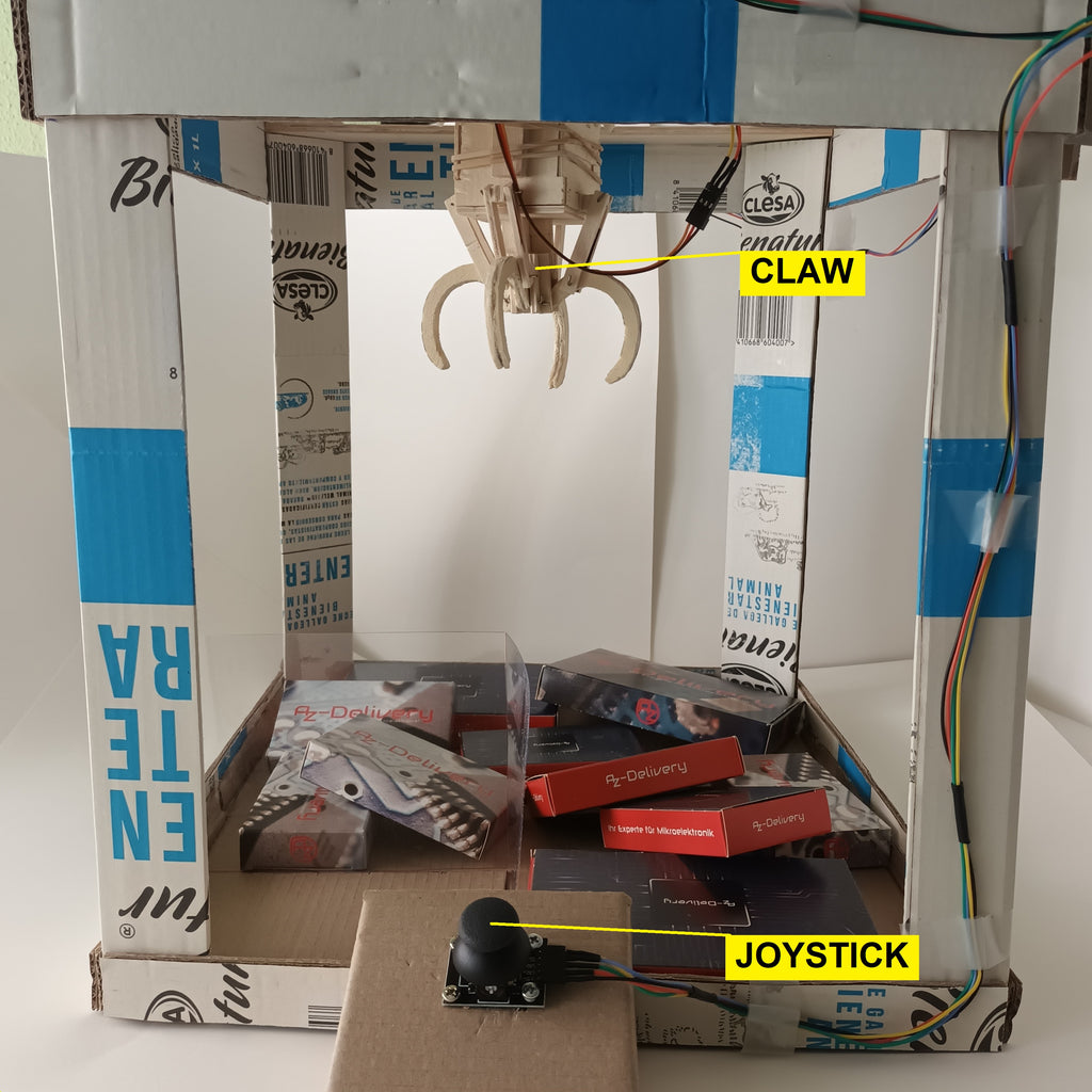
I use three 28BYJ48 stepper motors and their corresponding ULN2003 drivers. One motor is for forward or backward movement, another is for right or left movement of the claw carriage, and the third motor is used to raise or lower the claw. To control the movement of the carriage, I use the KY-023 joystick module, and for opening and closing the claw, I use the MG90s servo motor. I also use four KY-10 modules with optocoupler sensors to detect the end positions of the motors. The gripper will then simply continue in the opposite direction at the end of the path. The sensor is also used to make the gripper open when it reaches the "home" position. All this is controlled by an AZ-MEGA 2560 microcontroller.


 |
 |


Description of the functionality and the sketch
The motors will rotate at two speeds. The low speed is used for more precise control of the movement of the gripper using the joystick. Once it is above the object, the button on the joystick is pressed and it moves down. Once it has reached its destination there, the servo motor closes the claw. This is followed by a movement upwards, then sideways, and then forwards. Always when the gripper has reached its starting position of the respective distance. Then the claw is opened and the object falls out.
I will now explain the sequence of the sketch.
In the beginning, we include the servo library. With it, we can create a servo object.
#include <Servo.h>
Servo servo_claw;
Three variables are declared and defined for the joystick. They contain the pin numbers of the probe and the axes. X- and Y-position are analog values of two potentiometers. Therefore these connections are connected to the analog pins of the microcontroller.
const int SW_pin = 6;
const int X_pin = 0;
const int Y_pin = 1;
Next, variables are declared for the use of the stepper motors. speed_motor defines the speed. The variable stepCounter describes the position in the array stepsLookup. The motors must perform 4076 steps to complete a full turn. This value is contained in the variable stepsPerRev. numSteps is the number of elements of the array. stepsLookup[] contains the steps of the motors in half-phase order.
int speed_motor = 1200;
int stepCounter = 0;
int stepsPerRev = 4076;
const int = numSteps;
const int stepsLookup[numSteps] = { B1000, B1100, B0100, B0110, B0010, B0011, B0001, B1001 };
Four optocoupler sensors are used to limit carriage travel. The maximum limit (limit_sensor) and the minimum limit (home_sensor), are the outer limits. At this position, the gripper opens. The following variables define the pin numbers of the sensors on the microcontroller
int home_sensor_X = 53;
int limit_sensor_X = 52;
int home_sensor_Y = 51;
int limit_sensor_Y = 50;
and the variables to store the state of each sensor
int home_sensor_X_value;
int limit_sensor_X_value;
int home_sensor_Y_value;
int limit_sensor_Y_value;
Now follows the setup()-function.
First, the Serial Monitor is initialized so that we can see the signal status of our components.
Serial.begin(9600);
The next command configures the pin of the microcontroller for the button of the joystick as input. The pin uses the internal pull-up resistor. This makes the pin "active low".
pinMode(SW_pin, INPUT_PULLUP);
The reason for enabling the internal resistor is to provide stability to the measured value and to avoid an additional resistor in our circuit. With the pull-up mode configuration, the microcontroller pin is supplied with +5 Vdc while the button is not pressed. As a result, it has a HIGH level. When the button is pressed, the voltage is diverted to the ground and the level of the pin goes LOW. Thus the button press is detected.
To use the servo motor, the following must be done with the attach()-command to pass the pin number. The write()-command transfers the initial position (gripper open) of the servo motor in degrees.
servo_claw.attach(5);
servo_claw.write(50);
In setup() we also set the pin numbers of the microcontroller to which the three stepper motors will be connected. They have to be configured as output because we will send the corresponding signals to the drivers for the forward or reverse running of the motors.
The connections of the X-axis motor driver:
pinMode (29, OUTPUT);
pinMode (28, OUTPUT);
pinMode (27, OUTPUT);
pinMode (26, OUTPUT);
The connections of the Y-axis motor driver:
pinMode (25, OUTPUT);
pinMode (24, OUTPUT);
pinMode (23, OUTPUT);
pinMode (22, OUTPUT);
The connections for the gripper motor driver:
pinMode (33, OUTPUT);
pinMode (32, OUTPUT);
pinMode (31, OUTPUT);
pinMode (30, OUTPUT);
Now the pins to which the four optocoupler sensors have been connected must be configured as inputs.
pinMode(home_sensor_X, INPUT);
pinMode(limit_sensor_X, INPUT);
pinMode(home_sensor_Y, INPUT);
pinMode(limit_sensor_Y, INPUT);
At the end of the setup()-block, two loops are implemented to position the claw carriage in the "home" position of the X and Y axis after power on. It is a counting loop, in which with each step a call of the function return_name_axis_home() is executed. I explain here the loop in connection with the X-axis. The other axis is controlled identically.
In return_X_axis_home() the stepCounter is incremented and reset when the value of the variable numSteps is equal to. Its value is 8. After that X_axis_positioning_home() is called and the stepCounter is passed. The variable stepCpunter is the index of the array stepsLookup[]. It is passed to X_axis_positioning_home() . There each bit is read individually and its value is output to the respective pin. If the optocoupler sensor is HIGH the "Home" position has been reached and the motor is switched off. For this motor_X_off() is called. In the function, the pins of the motor are set to LOW, i.e. off. In the parent for loop, the variable speed_motor is used to determine the speed of the motor as a pause.
When the X-axis is in the home position, the same process is executed for the other axis to bring it to the home position. Only the name of the functions changes.

Once the two axes are in the home position, loop() is executed. First, the state of the switch and the values of the joystick axes, as well as the four optocoupler sensors, are read out. Their data and states are output via the serial monitor.
Serial.print("Switch: ");
Serial.print(digitalRead(SW_pin));
Serial.print("\n");
Serial.print("X-axis: ");
Serial.print(analogRead(X_pin));
Serial.print("\n");
Serial.print("Y-axis: ");
Serial.println(analogRead(Y_pin));
Serial.print("\n\n");
delay(20);

home_sensor_X_value = digitalRead(home_sensor_X);
Serial.print("Home sensor X: ");
Serial.println(home_sensor_X_value);
limit_sensor_X_value = digitalRead(limit_sensor_X);
Serial.println(limit_sensor_X_value);
home_sensor_Y_value = digitalRead(home_sensor_Y);
Serial.print("Home sensor Y: ");
Serial.println(home_sensor_Y_value);
limit_sensor_Y_value = digitalRead(limit_sensor_Y);
Serial.print("Limit sensor Y: ");
Serial.println(limit_sensor_Y_value);
The following if statements react to changes in the X and Y axes of the joystick.
Four directions and the push of a button are possible. The movements are restricted by limited values. Outside these values, the motors do not move. But it is possible to change the direction when the end of the track is reached.
if (analogRead(X_pin)>450 && analogRead(X_pin)<550) {
  motor_X_off();
}

if (analogRead(X_pin)>=551) {
  left_hand_movement();
}

if (analogRead(X_pin)<=449) {
  right_hand_movement();
}
If the read value is greater than or equal to 551, the call to the method left_hand_movement()to move the gripper to the left on the X-axis. The state of the microcontroller pins is determined by HIGH to LOW and vice versa to activate the motor coils in the half-phase sequence and perform the corresponding movement. When a complete sequence is executed, the optocoupler sensor for the "home position" of the axis measures the value and a test is performed with a simple condition. As long as the value LOW the motor can continue its movement to the left. If, when checking the condition, the value is HIGH, the method right_hand_movement() is called. The gripper continues to move in the opposite direction.
void left_hand_movement() {
  digitalWrite(29, LOW);
  digitalWrite(28, LOW);
  digitalWrite(27, HIGH);
  digitalWrite(26, LOW);
    delayMicroseconds(speed_motor);
  digitalWrite(29, LOW);
  digitalWrite(28, LOW);
  digitalWrite(27, HIGH);
  digitalWrite(26, HIGH);
    delayMicroseconds(speed_motor);
  digitalWrite(29, LOW);
  digitalWrite(28, LOW);
  digitalWrite(27, LOW);
  digitalWrite(26, HIGH);
    delayMicroseconds(speed_motor);
  digitalWrite(29, HIGH);
  digitalWrite(28, LOW);
  digitalWrite(27, LOW);
  digitalWrite(26, HIGH);
    delayMicroseconds(speed_motor);
  digitalWrite(29, HIGH);
  digitalWrite(28, LOW);
  digitalWrite(27, LOW);
  digitalWrite(26, LOW);
    delayMicroseconds(speed_motor);
  digitalWrite(29, HIGH);
  digitalWrite(28, HIGH);
  digitalWrite(27, LOW);
  digitalWrite(26, LOW);
    delayMicroseconds(speed_motor);
  digitalWrite(29, LOW);
  digitalWrite(28, HIGH);
  digitalWrite(27, LOW);
  digitalWrite(26, LOW);
    delayMicroseconds(speed_motor);.
  digitalWrite(29, LOW);
  digitalWrite(28, HIGH);
  digitalWrite(27, HIGH);
  digitalWrite(26, LOW);
    delayMicroseconds(speed_motor);
  home_sensor_X_value = digitalRead(home_sensor_X);
  if (home_sensor_X_value == HIGH) {
    right_hand_movement();
  }
}
If, on the other hand, the measured value of the X-axis of the joystick was less than or equal to 449, the method right_hand_movement() would be called to move the gripper to the right on the X-axis. The order of state change of the microcontroller pins connected to the X motor driver is reversed as explained above, so that the movement of the motor is to the right. As in the previous method, when each complete sequence is performed, the readout of the optocoupler sensor is performed. However, in this case, it is the sensor on the other side. If the sensor responds, the method left_hand_movement() is called so that the gripper is moved again in the opposite direction.
void right_hand_movement(){
        digitalWrite(29, LOW);
        digitalWrite(28, LOW);
        digitalWrite(27, LOW);
        digitalWrite(26, HIGH);
          delayMicroseconds(speed_motor);
        digitalWrite(29, LOW);
        digitalWrite(28, LOW);
        digitalWrite(27, HIGH);
        digitalWrite(26, HIGH);
          delayMicroseconds(speed_motor);
        digitalWrite(29, LOW);
        digitalWrite(28, LOW);
        digitalWrite(27, HIGH);
        digitalWrite(26, LOW);
          delayMicroseconds(speed_motor);
        digitalWrite(29, LOW);
        digitalWrite(28, HIGH);
        digitalWrite(27, HIGH);
        digitalWrite(26, LOW);
          delayMicroseconds(speed_motor);
        digitalWrite(29, LOW);
        digitalWrite(28, HIGH);
        digitalWrite(27, LOW);
        digitalWrite(26, LOW);
          delayMicroseconds(speed_motor);
        digitalWrite(29, HIGH);
        digitalWrite(28, HIGH);
        digitalWrite(27, LOW);
        digitalWrite(26, LOW);
          delayMicroseconds(speed_motor);
        digitalWrite(29, HIGH);
        digitalWrite(28, LOW);
        digitalWrite(27, LOW);
        digitalWrite(26, LOW);
          delayMicroseconds(speed_motor);
        digitalWrite(29, HIGH);
        digitalWrite(28, LOW);
        digitalWrite(27, LOW);
        digitalWrite(26, HIGH);
          delayMicroseconds(speed_motor);
        limit_sensor_X_value = digitalRead(limit_sensor_X);
        if (limit_sensor_X_value == HIGH) {
              left_hand_movement();
        }
}
For the movements of the joystick in the Y-direction, three conditions have been programmed for the X-axis, which is executed depending on the value at a certain time. The explanations of the functions for this axis are the same as for the previous ones. Only the names of the functions, the optocoupler sensors, the variables for reading the values of the sensor for the maximum limit, and the "Home" position change.
Now that the movement of the claw along the axes has been implemented, the movement of the claw itself is still missing. It must be successively lowered, closed, raised, brought to the home position of the X and Y axes, and opened there to drop the picked-up object at the push of a button.
The pin for the button is low-active, as described above. Its state is HIGH if it is not actuated. The motor for the up and down movement of the claw is not moved.
if (digitalRead(SW_pin) == HIGH) {
  motor_claw_off();
}
In the function motor_claw_off() all pins for the motor driver are set to LOW. This function is called when the named condition is met.
void motor_claw_off() {
  digitalWrite(33, LOW);
  digitalWrite(32, LOW);
  digitalWrite(31, LOW);
  digitalWrite(30, LOW);
}
If you press the joystick, the button is pressed. This causes the pin to go LOW. The previous condition is not fulfilled. The following lines of code are then executed. The condition LOW is tested here. If this condition is fulfilled, loops are run through for the movements.
if (digitalRead(SW_pin) == LOW) {

  for (int i = 0; i < stepsPerRev * 4.5; i++) {
    clockwise();
    delayMicroseconds(speed_motor);
  }
  delay(1000);
  for (int pos=50; pos<120; pos +=1) {
    servo_claw.write(pos);
  }
  delay(1000);

  for (int i = 0; i < stepsPerRev * 4.5; i++) {
    anticlockwise();
    delayMicroseconds(speed_motor);
  }
  delay(1000);

  for (int i = 0; i < stepsPerRev * 2; i++) {
    return_X_axis_home();
    delayMicroseconds(speed_motor);
  }

  for (int i = 0; i < stepsPerRev * 2; i++) {
    return_Y_axis_home();
    delayMicroseconds(speed_motor);
  }

  for (int pos=120; pos>50; pos -=1) {
    servo_claw.write(pos);
  }

}
First, the gripper is lowered. The motor makes four and a half revolutions. This value depends on the height of the construction. In the beginning, the variable stepsPerRev was declared at the beginning. Its value is responsible for one complete revolution. For the movement all the way down, this value must be multiplied by 4.5. Inside the loop, the function clockwise() is called. This rotates the motor clockwise and lowers the gripper. After the four and a half revolutions, a pause of 1 s is inserted.
for (int i = 0; i < stepsPerRev * 4.5; i++) {
  clockwise();
  delayMicroseconds(speed_motor);
}
delay(1000);
The motor works in a half-phase sequence. There are eight combinations to excite the coils and thereby rotate the axis of the motor. In the clockwise()-function there is the counter stepCounterwhich can take values from 0 to 7. This value is the index for the array stepsLookup[]. As already mentioned, each element consists of four bits. The function setOutput() is passed the index. In it the bits at the positions in the array are read and output to the motor driver pins.
void clockwise() {
  stepCounter++;
  if (stepCounter >= numSteps) {
    stepCounter = 0;
  }
  setOutput(stepCounter);
}
void setOutput(int step) {
        digitalWrite(30, bitRead(stepsLookup[step], 0));
        digitalWrite(31, bitRead(stepsLookup[step], 1));
        digitalWrite(32, bitRead(stepsLookup[step], 2));
        digitalWrite(33, bitRead(stepsLookup[step], 3));
}
In the course of the various loops, one moves the servo motor with the command servo_claw.write(pos) from the 50-degree position (gripper open) to the 120-degree position (gripper closed). After that, it pauses again for one second.
for (int pos=50; pos<120; pos +=1) {
  servo_claw.write(pos);
}
delay(1000);
The function anticlockwise() function is similar to the clockwise(). The difference is that the counter is not incremented but decremented. Here it is also limited from 7 to 0.
void anticlockwise() {
        stepCounter--;
        if (stepCounter < 0) {
    stepCounter = numSteps - 1;
        }
        setOutput(stepCounter);
}
As soon as the gripper is in its original position, it is moved to the home position of the X and Y axes. In the beginning, I have already shown which functions are used to bring the gripper "home". The methods are called one after the other in the loops here.
/****** Positioning of X-axis motor in home position ******/
for (int i = 0; i < stepsPerRev * 2; i++) {
  return_X_axis_home();
  delayMicroseconds(speed_motor);
}

/****** Positioning of Y-axis motor in home position ******/
for (int i = 0; i < stepsPerRev * 2; i++) {
  return_Y_axis_home();
  delayMicroseconds(speed_motor);
}
When both axes are in the initial position, only the gripper has to be opened. To do this, the degree of the servo motor must be changed from 120 degrees (closed) to 50 degrees.
for (int pos=120; pos>50; pos -=1) {
  servo_claw.write(pos);
}
I hope you found this project interesting and as always, I look forward to suggestions in the comments.
If the video does not display, please check your browser's cookie settings.


