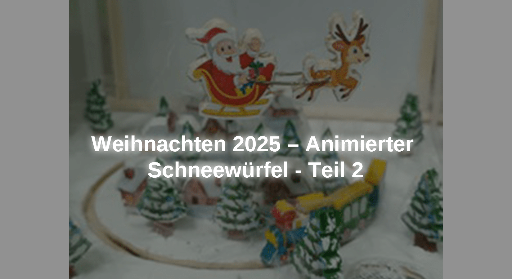
In the second part of the Christmas project, we equip the device with an MP3 player module, an amplifier and two mini speakers. A WS2812B LED display is also added to display congratulatory messages. Images can also be added if desired. To do this, the sketch must be changed. Lastly, we add four fans to create the effect of a snowstorm. To do this, small pieces of feathers from a feather duster must be added, as they weigh little and move with a slight air current inside the urn.
If desired, the transparent urn can be omitted, making the entire project look different even when the fans are not in use. Let's start developing this second part of the project.
The materials required for the entire project are:
-
1x PAM8403 Digital Mini Audio Amplifier 2x 3 Watt DC 5V Board with Potentiometer
-
1x 4 channel relay module 5V with optocoupler low level trigger
-
1x 5 Kohm potentiometer
The required software is:
● Arduino IDE
● Adafruit GFX library (Arduino Adafruit_GFX.h)
● Adafruit NeoPixel library (Arduino Adafruit_NeoPixel.h)
● SoftwareSerial library (SoftwareSerial.h)
● Adafruit_NeoMatrix library (Adrafruit_NeoMatrix.h)
● DFPlayer Mini library from DFRobot (DFRobotDFPlayerMini.h)
● SPI.h library (included in the Arduino IDE)
● 001.mp3
● 002.mp3
● 003.mp3
● snow_cube_animated_part_2.ino
The drawings of the characters are:
● Zug.jpg
Circuit diagram and description of the modules used in the second part of the project

Drawing 2 – Snow Cube Drawing Part 2
Project assembly
To complete the project structure, a back panel was added to install the 256 LED WS2812B matrix and all electronics on this back of the panel. To install the LED panel and a translucent panel (in this case a white sheet of paper), rails were attached into which the edges of the LED panel and the translucent panel are inserted. The dimensions of the newly added plate are shown in the following image. Also added the drawing of the lower part of the platform of the fans and the shafts.

Figure 1 – WS2812B panel dimensions

Image 2 - WS2812B panel
Description of the sketch
After attaching the bracket for installing the WS2812B LED matrix and electronic components, we start analyzing the sketch. At the beginning of each sketch, the libraries required to use the modules must first be inserted. In this case, three libraries are required to use the LED panel in this project. The following three libraries are required to display text. The library Adafruit_GFX.h is needed to display primitive graphics such as lines, circles, etc. Since our LED panel is an LED grid, we also need the library Adafruit_NeoMatrix.h to be able to control a group of LEDs on the panel. The last library we include is Adafruit_NeoPixel.h, which is required to control the three internal LEDs of each LED.
#include <Adafruit_GFX.h>
#include <Adafruit_NeoMatrix.h>
#include <Adafruit_NeoPixel.h>
The following Libraries need to be added: <SoftwareSerial.h>, which allows the microcontroller to enable each digital pin for serial communication. This is required to use the MP3 playback module and serial console to display messages at startup. <DFRobotDFPlayerMini.h> is the library that enables the functions required to use the MP3 player module.
#include <SoftwareSerial.h>
#include <DFRobotDFPlayerMini.h>
Next, an object needs to be implemented to use the MP3 playback module. This is what the object is mySoftwareSerial from the library <SoftwareSerial.h> implemented to indicate to the microcontroller the digital pins to be used for serial communication with the module. In this project, digital pin 15 of microcontroller is used to receive data from MP3 module and digital pin 14 is used to send data to MP3 module. To use the methods and control commands of the MP3 module, such as: B. adjust the volume or start playing an MP3 file, the object myDFPlayer from the library <DFRobotDFPlayerMini.h> created.
SoftwareSerial mySoftwareSerial(15, 14);
DFRobotDFPlayerMini myDFPlayer;
The next line creates a first constant with the number of LEDs (256) of the WS2812B LED matrix and a second to indicate that the data line of the matrix is connected to port 16 of the microcontroller. We need these two constants to be able to work with the LED matrix.
#define NUM_LEDS 256
#define PIN 16
In order to be able to control the module with 4 relays, the microcontroller must know to which ports the individual control lines of the relay module are connected. To do this, 3 constants are created, the values of which must correspond to the numbers of the ports to which the control lines of the relay module are connected.
#define FAN_1 17
#define FAN_2 18
#define FAN_3 19
An object with the name is then created matrix from the library Adafruit_NeoMatrix.h implemented to display text on the LED panel. The arguments or parameters to be specified are:
● Number of LEDs in the width and height of the panel (16 LEDs in width and 16 LEDs in height) and the PIN of the microcontroller to which the panel's data line is connected.
● Location of LED number 0 on the control panel (the number of LEDs is 256, but the numbering starts at 0 and ends at 255). LED 0 is located at the bottom right of the control panel.
● Arrangement of LEDs in the Matrix and Consecutive Numbering: The LEDs are arranged in columns so that when LED number 0 is in the bottom right corner, LED number 1 is the top one. When LED number 15 (first column and last LED) is reached, the next LED (number 16) is to the left of it, i.e. h. the numbering runs in a zigzag like a snake.
● The arrangement and wiring of the three internal LEDs, the internal arrangement is green, red and blue (NEO_GRB). The last parameter is the working frequency (800 KHz).
Adafruit_NeoMatrix matrix = Adafruit_NeoMatrix(16, 16, PIN,
NEO_MATRIX_BOTTOM + NEO_MATRIX_RIGHT +
NEO_MATRIX_COLUMNS + NEO_MATRIX_ZIGZAG,
NEO_GRB + NEO_KHZ800);
Then the variable must x can be created in which the number of LEDs that the panel has in width is first saved. This value is set with the command matrix.width() determined. This data was previously created when the object was created matrix entered. This variable is in a condition if used to count the number of columns that need to be moved left to display a message on the panel. This condition is inside a loop do-while. The method of presenting the text will be explained later.
int x = matrix.width();
Después se implementa el object picture de la libreria Adafruit_NeoPixel.h with the number of the LEDs of the panel, the pin of connection to the microcontroller, the disposition and cable of the three internal LEDs, the internal disposition of the LEDs is green, red and blue (NEO_GRB). The ultimate value of the arguments is the working frequency (800 KHz). These objects and definitions of posterior colors are necessary if they represent images in the LED panel, but they do not need to be represented alone by text.
Adafruit_NeoPixel picture(NUM_LEDS, PIN, NEO_GRB + NEO_KHZ800);
A range of colors is defined, even if not all of them are used.
uint32_t p_red = picture.Color(150,0,0);
uint32_t p_green = picture.Color(0,150,0);
uint32_t p_blue = picture.Color(0,0,150);
uint32_t p_yellow = picture.Color(150,150,0);
uint32_t p_purple = picture.Color(150,0,150);
uint32_t p_light_blue = picture.Color(0,150,150);
uint32_t p_white = picture.Color(150,150,150);
uint32_t p_maroon = picture.Color(150,51,0);
uint32_t p_black = picture.Color(0,0,0);
The lines created in the first part of the project, which represent the definition of the microcontroller pins to which the contacts of the L298N module that controls each motor will be connected, remain unchanged.
#define enable_Santa_motor 7
#define connection_1_Santa_motor 5
#define connection_2_Santa_motor 6
#define enable_train_motor 2
#define connection_1_train_motor 3
#define connection_2_train_motor 4
The constants for the six LEDs are also retained, which are assigned the number of the port of the microcontroller to which they are connected.
#define led_house_1 8
#define led_house_2 9
#define led_house_3 10
#define led_house_4 11
#define led_house_5 12
#define led_house_6 13
After the libraries have been added and the variables required for this second part of the project have been defined, the initial conditions of the added modules must be initialized and set. This is done in the method setup(), which begins the description of the code it contains.
First, the parameters of the LED panel must be initialized and configured so that it can display text. The panel needs to be initialized by the object matrix with matrix must be initialized. begin(); The text must begin its display on the right side of the panel and end on the left using the command matrix use. setTextWrap(false.false) prevents the text that appears on the left from appearing on the right again. The brightness of the LEDs is adjusted with the command matrix.setBrightness(7) set to a value of 7 to display the text. This is low brightness. The initial color of the text is set with the command matrix.setTextColor(matrix.Color(Red, Green, Blue)) , as both the red and green LEDs display the values 0 are completely switched off and the blue LED with the value 254 is switched on.
matrix.begin();
matrix.setTextWrap(false.false);
matrix.setBrightness(7);
matrix.setTextColor(matrix.Color(0, 0, 254));
If you want to display graphics on the LED panel, initialize the object picture with picture. begin()to display images on the LED panel if desired. In this project this has not been chosen but it is initialized in this method and if you want to display images you just need to add the required code for the image to be displayed in the method loop() add. It ends with a 2 second pause.
picture.begin();
delay(2000);
Next, the MP3 playback module needs to be initialized and communicated with the microcontroller mySoftwareSerial.begin(9600), where 9600 is the data transfer speed in baud. In addition, communication with the serial monitor is carried out via Serial.begin (115200) at a speed of 115200 baud (the speed must be selected at the bottom right of the Serial Monitor when the console is opened) in order to display the messages regarding the initialization status or errors of the MP3 module. With the line Serial.println („Christmas 2025: Snow ball”) a message is sent to the serial console. To view this message, it is very important to change the speed value in the serial console.
mySoftwareSerial.begin(9600);
Serial.begin(115200);
Serial.println ("Christmas 2025: Snowball");
The next thing to check in the code is the initialization of the MP3 module. This is done using a conditional statement if used. In the instruction if The code within the curly braces will be executed if the condition of its parameter is true. In this case checks whether the MP3 module has not been initialized for some reason. The negated initialization was with the symbol ! written. This symbol is used as a negation method so that if the module is not initialized, the condition is true and the code inside the curly brackets is executed and the serial console reports to check the connections and microSD card insertion. If the MP3 playback module is initialized correctly, the condition is not met and the code described above will not be executed. The method setup () continued to run via the serial console with the line Serial.println(F("Correct DFPlayer initialization.")) to report that the MP3 playback module has been initialized correctly.
Serial.begin(115200);
Serial.println ("Christmas 2025: Snowball");
if (!myDFPlayer.begin(mySoftwareSerial)) {
Serial.println(F("Error initializing mp3 module:"));
Serial.println(F("1. Please check the connections!"));
Serial.println(F("2. Please insert the microSD memory!"));
while(true){
delay(0);
}
}
Serial.println(F("Correct DFPlayer initialization."));
After the initialization code of the MP3 module, the pins of the microcontroller that are used to control the motors are configured. They have to be used as output signal pins pinMode(pin_number, OUTPUT) configured because they need to send signals to the L298N control module pins.
pinMode(enable_Santa_motor,OUTPUT);
pinMode(connection_1_Santa_motor,OUTPUT);
pinMode(connection_2_Santa_motor,OUTPUT);
pinMode(enable_train_motor,OUTPUT);
pinMode(connection_1_train_motor,OUTPUT);
pinMode(connection_2_train_motor,OUTPUT);
The pins of the microcontroller to which the LEDs for interior lighting of the houses are connected must also be configured as output signal pins, as they have to supply voltage for the LEDs to light up.
pinMode(led_house_1,OUTPUT);
pinMode(led_house_2,OUTPUT);
pinMode(led_house_3,OUTPUT);
pinMode(led_house_4,OUTPUT);
pinMode(led_house_5,OUTPUT);
pinMode(led_house_6,OUTPUT);
To program the method setup() To complete, all that remains is to configure the ports of the microcontroller to which the relay module that controls the switching on and off of the fans is connected. These must be outputs and the initial state must be high, sending 5Vdc to the relay module.
pinMode(FAN_1, OUTPUT);
digitalWrite(FAN_1, HIGH);
pinMode(FAN_2, OUTPUT);
digitalWrite(FAN_2, HIGH);
pinMode(FAN_3, OUTPUT);
digitalWrite(FAN_3, HIGH);
After the initial conditions of all modules and components of the project have been configured, the method must now be configured loop() be programmed so that the entire system carries out the desired movements, sounds and light messages. The first line shows the volume of the sound playback myDFPlayer.volume(20) set to a value of 20 out of 30, resulting in the file named 001.mp3 myDFPlayer.play (001) played. This file must be stored on the microSD card inserted in the MP3 playback module and will play the train whistle sound exactly when the train starts moving. With the line delay(1700) sets the time between the preparation of the audio file and its playback.
myDFPlayer.volume(20);
myDFPlayer.play(001);
delay(1700);
Next, the movement of the train is programmed, using the line analogWrite(pin_number, value) the speed of the motor is set with an analog value whose maximum value is 244. The two are used for the direction of rotation of the motor digitalWrite(pin_number, state) defined lines are used. If the motor rotates in the opposite direction to the desired direction, this can be corrected either by changing the status of these two lines or by swapping the cables between the L298N module and the motor.
analogWrite(enable_train_motor,128);
digitalWrite(connection_1_train_motor,HIGH);
digitalWrite(connection_2_train_motor,LOW);
To light the LED, you can change the position of the pin to the connection. Normally, it has a voltage on a microcontroller board or is reinicia, the initial state of the ports is low (LOW), it declines, no lower voltage, but it is necessary to change the state to a high (HIGH) to obtain a voltage of 5 Vcc. It is realized with the command digitalWrite(pin_number, STATE). Después de encender cada LED, are realized in a pause of 1 second.
digitalWrite(led_house_1, HIGH);
delay(1000);
digitalWrite(led_house_2, HIGH);
delay(1000);
digitalWrite(led_house_3, HIGH);
delay(1000);
digitalWrite(led_house_4, HIGH);
delay(1000);
digitalWrite(led_house_5, HIGH);
delay(1000);
digitalWrite(led_house_6, HIGH);
delay(1000);
When all the houses are lit up, Santa Claus should start to walk through the village, but before that the ringing of the reindeer bells should be heard, for which the volume of the sound should be adjusted myDFPlayer is set to a value of 25 out of 30. volume(25), then the file with the name 002.mp3 is included myDFPlayer. play(002). This file must be saved on the microSD card inserted in the MP3 playback module and reproduces the sound of the bells. With the line delay(800) sets the time between the preparation of the audio file and its playback.
myDFPlayer.volume(25);
myDFPlayer.play(002);
delay(800);
Then Santa starts rotating around the village when the line analogWrite(pin_number, value) is executed. The speed of the motor is set with an analog value, the maximum value of which is 244, as already mentioned in the first part. The speed was too high, but if the value of this variable is below 128, the motor will not rotate, which is why it was decided to install a 5 Kohm potentiometer. In the positive polarity line leading from the L298N module to the motor, the desired speed is set by adjusting the value of this potentiometer. The two are used for the direction of rotation of the motor digitalWrite(pin_number, state) defined lines are used. If Santa's motor rotates in the opposite direction, this can be corrected either by changing the status of these two wires or by swapping the cables from the L298N module to the motor. With the line delay(2000) There is a pause of 2 seconds until the next line of code is executed.
analogWrite(enable_Santa_motor,128);
digitalWrite(connection_1_Santa_motor,HIGH);
digitalWrite(connection_2_Santa_motor,LOW);
delay(2000);
The volume of the sound playback is then adjusted myDFPlayer.volume(15) set to a value of 15 out of 30 to include the audio file named 003.mp3 myDFPlayer. play(003) set. This file must be saved on the microSD card inserted in the MP3 player module and plays a Christmas melody.
myDFPlayer.volume(15);
myDFPlayer.play(003);
The following three lines change the status of the ports that the relay module is connected to from "high" to "low", which causes the relay module to activate the three relays and the fans are energized and begin to spin, introducing air into the urn, which should cause the down flakes to move in all directions.
digitalWrite(FAN_1,LOW);
digitalWrite(FAN_2,LOW);
digitalWrite(FAN_3,LOW);
Then the next line of code show_message_az() executed. This line is a call to execute the method with that name, which executes the code contained in that method. After completion of execution, the program returns to the line delay (3000) executed to take a 3 second pause before the next line of code loop() is executed.
show_message_az();
If the method show_message_az() is called, it will be executed, and there will be a loop inside its curly braces do-whilewhich will be executed as long as the condition while is true. As we remember, the variable was x originally initialized with the number of LEDs that the panel has in width, i.e. 16. This loop is executed until the condition while the value x reached by -109, which is the last execution, since -109 is greater than -110 (they are negative numbers), the command block do executed.
void show_message_az() {
do {
…
…
…
} while (x > -110);
}
Inside the loop do The first instruction to be executed is to turn off all LEDs on the panel with the instruction matrix.fillScreen(0). The second statement sets the text color matrix.setTextColor(matrix.Color(254, 0, 0)) set to red, with matrix. setCursor(x, 5) the cursor is placed in column 16 (i.e. the first column is moved 16 positions to the left) and line 5, then the text that is to be displayed in the panel is included matrix. print(F(" From AZ-Delivery ")). The following condition if is a counter that starts at 16 and goes to -110. It is used to set the value of the cursor x (the columns) to show the text and give the impression of movement. It decreases by one unit and executes the next instruction, viz matrix.show(), which lights up the corresponding LEDs for that position. With delay(35) There will be a 35 millisecond pause as this is the end of the loop. The review will then be carried out while executed which says that the loop starts over from the beginning as long as the value of x is greater than -110. To summarize, configure the color of the text, move the columns and turn on the corresponding LEDs for displaying each part of the letters of the text and with the delay of 35 milliseconds gives the impression of movement in the text.
matrix.setTextColor(matrix.Color(254, 0, 0));
matrix.setCursor(x, 5);
matrix.print(F("From AZ-Delivery "));
if(--x < -110) {
x = matrix.width();
}
matrix.show();
delay(35);
After this method completes, it returns to the next statement from which the call was made, thereby executing a 3 second wait.
delay(3000);
With the calls to the methods show_message_germany() and show_message_spanish() These methods are carried out in accordance with the previously explained method show_message_az() resemble.
If you want images in addition to text in your Christmas blog post 2022 “3rd Advent: Animated LED Christmas decorations – UPDATE” here are instructions on how to display images on both the AZ-MEGA2560 board and the AZ-ATmega328 board.
This project can also be done without fans and without the transparent urn. The look is different, but it still creates a unique feeling.
We from AZ-Delivery Vertriebs GmbH wish you a Merry Christmas, a successful New Year and lots of fun with your family.


